
Respuesta directa
Choose polyimide with rolled annealed copper for most flexible PCB projects because it survives reflow soldering and repeated dynamic bending. Polyester is only viable for low-cost static flex, and electrodeposited copper works only when the board bends once. For high-frequency signals, switch to LCP or PTFE-based laminates with stable dielectric properties. Verify bend radius and stackup with your manufacturer before finalizing the design.
The Default Flexible PCB Material and When to Use It
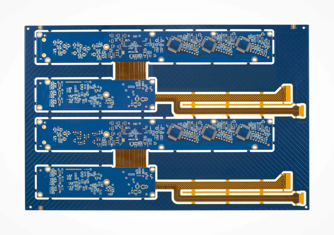
Polyimide is the default flexible PCB substrate for most flex and rigid-flex applications. It withstands soldering temperatures above 300°C, offers good dimensional stability, and can survive hundreds of thousands of flex cycles. Polyester is cheaper but cannot survive reflow soldering, so it is limited to static flex applications where the PCB is bent once during assembly and then remains fixed.
The engineering principle behind this choice is simple: the substrate must survive both the manufacturing process and the end-use environment. Polyimide's thermal stability makes it compatible with standard lead-free solder profiles, which typically peak between 240°C and 260°C. Polyester, with a glass transition temperature near 150°C, will soften and deform during reflow, causing trace distortion and delamination.
For rigid-flex boards—where rigid FR-4 sections connect through flexible hinges—polyimide remains the standard choice. The flex zones are typically single-layer polyimide, while the rigid zones use standard FR-4 laminates. This hybrid approach gives you the mechanical rigidity of a traditional PCB with the ability to fold the board into a compact enclosure.
When Polyester Makes Sense
Polyester is acceptable only when the PCB will be bent once during assembly and then held in a fixed position. Common examples include simple sensor tags, disposable medical devices, and low-cost LED strips. The material costs less than polyimide, but you must verify that your assembly process does not expose the board to temperatures above 150°C.
If you are considering polyester, confirm that your solder mask and ink systems are compatible with the substrate. Polyester has a lower surface energy than polyimide, which can cause adhesion failures for solder mask and conformal coatings. Your manufacturer should validate adhesion with a tape pull test before committing to the material.
Copper Selection: Rolled Annealed vs. Electrodeposited
Choose rolled annealed copper for dynamic flex applications where the circuit must bend repeatedly during use. Rolled annealed copper has a finer grain structure that resists work hardening and cracking. Electrodeposited copper is acceptable for static flex or rigid-flex boards with minimal flexing, but it will crack sooner under repeated bending.
The grain structure difference is the key engineering variable. Rolled annealed copper is mechanically worked and heat-treated to produce a uniform, fine-grained microstructure. This structure allows the copper to deform plastically without initiating micro-cracks. Electrodeposited copper, produced by electroplating onto a drum, has a columnar grain structure that is more susceptible to fatigue cracking under cyclic bending.
Copper weight is another critical factor. Standard flex PCBs use 0.5 oz/ft² (approximately 17.5 µm) or 1 oz/ft² (approximately 35 µm) copper. Thicker copper increases current-carrying capacity but reduces flexibility. For dynamic flex applications, stay with 0.5 oz/ft² unless your current requirements force a heavier weight. If you need higher current, consider widening the trace instead of increasing copper thickness.
Dynamic Flex Design Rules
For dynamic flex, follow these practical guidelines:
- Use a bend radius of at least 10 times the total PCB thickness
- Keep copper traces perpendicular to the bend axis where possible
- Avoid placing vias or through-holes in the flex zone
- Use teardrop-shaped trace terminations instead of sharp corners
- Specify rolled annealed copper in your fabrication drawing
For static flex, the bend radius can be reduced to 6 times the total thickness, and electrodeposited copper is acceptable. However, you should still avoid placing vias in the flex zone, as the copper plating inside the hole can crack and propagate into the trace.
High-Frequency Laminates for RF and High-Speed Signals
For RF or high-speed signals, use a high-frequency laminate such as a liquid crystal polymer (LCP) or a PTFE-based material. These materials have a lower and more stable dielectric constant and dissipation factor than standard polyimide. Verify the material's Dk and Df values at your operating frequency, and account for the fact that flex materials often have a higher loss than rigid FR-4.
Standard polyimide has a dielectric constant (Dk) around 3.4 and a dissipation factor (Df) near 0.005 at 1 GHz. While this is acceptable for many applications, it becomes problematic for high-frequency designs where signal integrity is critical. LCP materials offer a Dk near 2.9 with a Df below 0.002, while PTFE-based laminates can achieve even lower loss.
The trade-off is cost and mechanical behavior. LCP and PTFE materials are significantly more expensive than polyimide and may have different flex characteristics. PTFE, in particular, has a low coefficient of friction and can be difficult to bond with adhesives. Your manufacturer will need to validate the coverlay adhesion and the overall stackup before production.
Impedance Control in Flex Zones
When routing high-frequency signals through a flex zone, the impedance is affected by the bend itself. A sharp bend changes the effective dielectric spacing and can cause impedance mismatch, leading to reflections and insertion loss. For controlled impedance traces, maintain a consistent bend radius and avoid sharp creases.
Specify the impedance requirement in your fabrication drawing. For example, if you need a 50-ohm trace, state the frequency range and the allowable tolerance. The manufacturer can then select the appropriate copper weight and laminate thickness to achieve the target impedance. For differential pairs, keep the traces symmetric and equal in length to minimize skew.
Manufacturing Constraints and DFM Review
The most common mistakes in flexible PCB design are discovered during design for manufacturability (DFM) review. These errors create rework, delay quotes, and increase cost. Understanding the manufacturing constraints before you finalize your design will save time and money.
Common DFM Mistakes
- Specifying a bend radius smaller than the material allows. This causes cracking during flex testing or in-field failure. Always verify the minimum bend radius with your manufacturer for your specific stackup.
- Using electrodeposited copper for dynamic flex. The board may pass initial inspection but fail after thousands of cycles. Specify rolled annealed copper explicitly in your drawing.
- Placing vias in the flex zone. Vias create stress concentration points and are a common source of cracking. Move vias to rigid sections or use a rigid-flex design.
- Ignoring the coverlay or solder mask selection. The protective layer must be compatible with the substrate and the flex requirements. A stiff solder mask can reduce flexibility and cause cracking.
- Omitting the flex cycle count from the drawing. Without a specified cycle count, the manufacturer cannot select the correct material or validate the design.
Inspection and Testing
Flexible PCBs require different inspection methods than rigid boards. Visual inspection under magnification is used to check for surface cracks, delamination, and copper grain structure. For dynamic flex applications, a flex test fixture is used to cycle the board through the specified bend radius for the required number of cycles.
IPC-6012 covers the qualification and performance of rigid PCBs, and its principles apply to flexible boards for fabrication quality. IPC-TM-650 provides test methods for material properties such as peel strength, flexural endurance, and dielectric properties. Your manufacturer should be able to reference these standards when validating your design.
Decision Table for Flexible PCB Material Selection
Use the following table as a quick reference when selecting materials for your flexible PCB project.
| Application Condition | Substrate | Copper Type | Bend Radius (× thickness) | Typical Use Case |
|---|---|---|---|---|
| Dynamic flex, high temperature | Polyimide | Rolled annealed | ≥ 10× | Wearables, medical devices, robotics |
| Static flex, high temperature | Polyimide | Electrodeposited | ≥ 6× | Rigid-flex boards, folded assemblies |
| Static flex, low temperature | Polyester | Electrodeposited | ≥ 6× | Disposable sensors, LED strips |
| High-frequency RF, dynamic flex | LCP or PTFE | Rolled annealed | ≥ 10× | Antennas, 5G modules, radar |
| High-frequency RF, static flex | LCP or PTFE | Electrodeposited | ≥ 6× | RF interconnects, test fixtures |
> Practical note: The bend radius values in this table are starting points, not guarantees. Thicker copper, multiple layers, and the presence of stiff components like solder mask or coverlay all increase the minimum bend radius. Always request a flex test from your manufacturer before committing to production.
What to Provide to Your Manufacturer for an Accurate Quote
To get an accurate quote and avoid rework, provide your manufacturer with a complete fabrication drawing that includes the following information:
- Gerber files and a complete bill of materials (BOM)
- Flex material type (polyimide, polyester, LCP, PTFE)
- Copper weight and type (rolled annealed vs. electrodeposited)
- Coverlay or solder mask specification
- Surface finish requirements
- Minimum bend radius and flex cycle count
- Operating temperature range
- Impedance requirements for high-frequency traces
- Any IPC standards that apply to your design
The more complete your drawing, the more accurate your quote. A manufacturer cannot select the correct material or validate the stackup without knowing the flex cycle count and temperature range. If you are unsure about a specific parameter, ask for guidance before finalizing the design.
When you are ready to move forward, the process of selecting a manufacturing partner is just as important as selecting the material. Review the criteria in our guide on How to Choose the Best PCB Maker for Your Project to ensure your partner has the right capabilities. For a broader view of supplier evaluation, see How to Choose a Reliable PCB Manufacturer for Your Project. If your design includes vias, understand the trade-offs in How to Choose the Appropriate Via Hole Filling Types for Your PCB before finalizing the stackup.
For applications where you are comparing flexible substrates against rigid options, the material comparison in FR4 vs Rogers PCB Material: Which One Should I Choose for My Products? provides useful context. And if your project extends beyond the bare PCB into full device assembly, review the considerations in How to Choose a Suitable Box Build Assembly Manufacturer for Your Device to plan your complete supply chain.
Preguntas frecuentes
What is the default flexible PCB material and when should I use it?
Polyimide is the default for most flex and rigid-flex PCBs because it withstands soldering temperatures above 300°C, offers good dimensional stability, and can survive hundreds of thousands of flex cycles. Polyester is cheaper but cannot survive reflow soldering, so it is limited to static flex applications where the PCB is bent once during assembly and then remains fixed.
When should I use rolled annealed copper instead of electrodeposited copper?
Choose rolled annealed copper for dynamic flex applications where the circuit must bend repeatedly during use. Rolled annealed copper has a finer grain structure that resists work hardening and cracking. Electrodeposited copper is acceptable for static flex or rigid-flex boards with minimal flexing, but it will crack sooner under repeated bending.
How do I select a flexible PCB material for high-frequency signals?
For RF or high-speed signals, use a high-frequency laminate such as a liquid crystal polymer or a PTFE-based material. These materials have a lower and more stable dielectric constant and dissipation factor than standard polyimide. Verify the material's Dk and Df values at your operating frequency, and account for the fact that flex materials often have a higher loss than rigid FR-4.
What is the minimum bend radius for a flexible PCB?
The minimum bend radius depends on the material type, copper thickness, and the number of layers. A common rule of thumb is to use a bend radius of at least 10 times the total thickness for dynamic flex, and 6 times for static flex. Thicker copper and multiple layers require a larger bend radius. Always verify the manufacturer's recommended minimum bend radius for your specific stackup.
What information should I provide to a flex PCB manufacturer to get an accurate quote?
Provide the Gerber files, a complete BOM, and a detailed fabrication drawing that specifies the flex material type, copper weight, coverlay or solder mask, surface finish, and any impedance requirements. Also include the bend radius, flex cycle count, and the operating temperature range. This information lets the manufacturer select the correct material and validate the stackup for your application.
How do I verify that my flex PCB design will survive the required number of cycles?
Request a flex test from your manufacturer using a test fixture that matches your specified bend radius and cycle count. The test should be performed on a representative sample that includes the actual copper weight, coverlay, and any stiff components. For dynamic flex applications, this test is essential before committing to production.
> Engineering handoff note: How to Evaluate PCB Manufacturing Risk from PCB Design and EasyEDA Trends before the release package is frozen.
> Engineering handoff note: How to Choose the Right Manufacturer for Flex PCB Fabrication before the release package is frozen.
> Engineering handoff note: How to Choose the Right Materials for HDI PCB Fabrication before the release package is frozen.