
Direct Answer
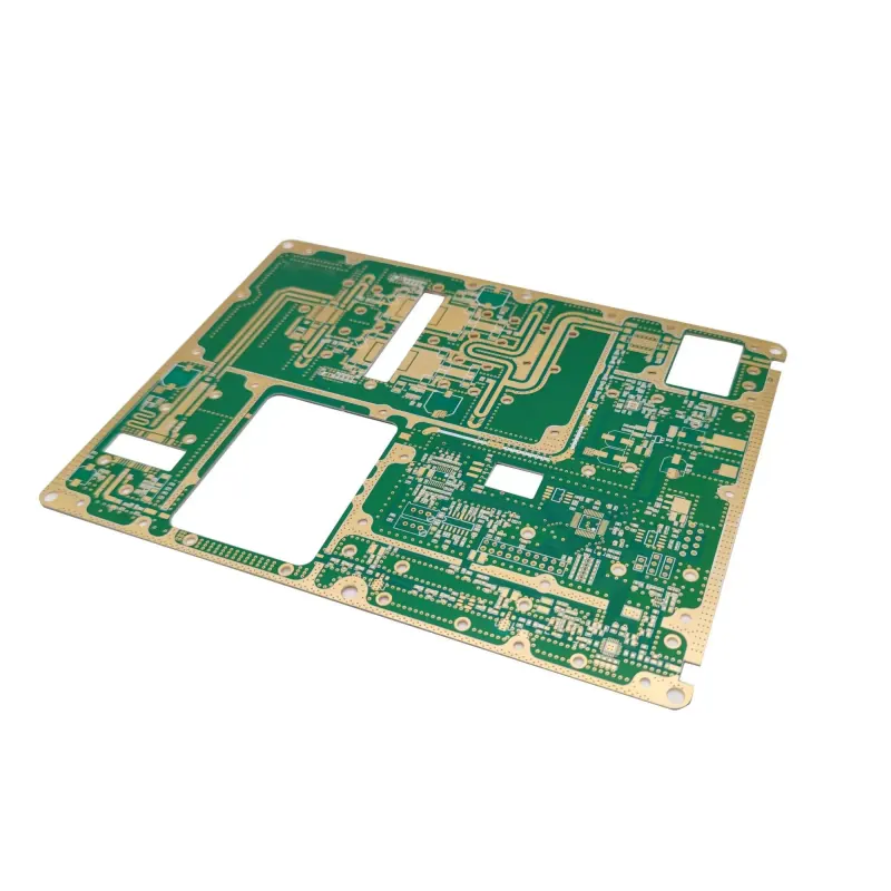
FR4 remains the go-to substrate for most PCB manufacturing due to its balance of cost, availability, and adequate performance for digital and low-frequency analog circuits. Rogers materials, while significantly more expensive, are engineered for high-frequency applications where signal loss, dielectric constant stability, and thermal conductivity directly impact product performance. Choose FR4 for products operating below 1 GHz with standard thermal and mechanical demands. Select Rogers when your design involves RF, microwave, 5G, radar, or high-speed digital signals above 1 GHz, or when managing heat in power-dense modules.
Material Properties and Performance Tradeoffs
FR4 is a composite of woven fiberglass cloth and epoxy resin, offering a dielectric constant (Dk) around 4.5 and dissipation factor (Df) of 0.02 at 1 MHz. These values shift with frequency, causing increased signal loss and impedance variation above 1 GHz. Its thermal conductivity is approximately 0.3 W/m·K, which limits heat spreading in high-power designs. Despite these limitations, FR4 excels in mechanical strength, moisture resistance, and compatibility with standard PCB fabrication processes like etching, drilling, and plating.
Rogers laminates, such as the RO4000® and RO3000® series, use ceramic-filled PTFE or hydrocarbon composites to achieve Dk values from 2.9 to 3.5 with Df as low as 0.001–0.004 at 10 GHz. This results in minimal signal attenuation and stable impedance in high-frequency PCBs. Thermal conductivity ranges from 0.5 to 1.2 W/m·K, improving heat dissipation in RF power amplifiers and antenna boards. The tradeoff is higher cost, increased brittleness during drilling, and sensitivity to etchants, requiring adjusted process parameters in PCB manufacturing.
When FR4 Is the Right Choice
For most consumer electronics, industrial controls, and IoT devices, FR4 provides sufficient performance. Applications like microcontroller boards, sensor interfaces, power supplies below 100W, and LED drivers operate well within FR4’s limits. In these cases, the focus shifts to optimizing PCB stackup, surface finish, and DFM rather than upgrading substrate material.
For example, a typical 4-layer IoT gateway with Bluetooth and Wi-Fi (2.4 GHz) can use FR4 if trace lengths are short and ground planes are solid. At these frequencies, FR4’s losses are manageable with proper impedance control and via stitching. Using Rogers here would add unnecessary cost without measurable performance gain.
Omini often recommends FR4 for prototype runs where design validation is the priority. Once the circuit is proven, teams may reevaluate material choice for production scaling—especially if moving to higher frequencies or power levels.
When Rogers Delivers Measurable Value
Rogers materials become essential in applications where signal integrity cannot be compromised. Radar systems in automotive ADAS, satellite communication modules, and 5G infrastructure rely on stable Dk and low Df to maintain beamforming accuracy and link margin. In these designs, even small variations in dielectric constant can detune antennas or distort pulse shapes.
High-speed digital designs exceeding 10 Gbps, such as SERDES interfaces or backplanes, also benefit from Rogers’ low loss. At these data rates, FR4’s dissipation factor causes excessive signal attenuation and jitter, leading to bit errors. Rogers preserves eye height and reduces the need for aggressive equalization.
Thermal management is another key factor. Power amplifiers in RF modules generate localized heat that FR4 struggles to spread. Rogers’ higher thermal conductivity helps move heat toward vias and heatsinks, improving reliability in thermally cycled environments.
Impact on PCB Stackup and DFM
Material choice directly influences PCB stackup design. Rogers’ lower Dk allows for wider traces to achieve the same impedance as FR4, which can ease etching and reduce copper usage. However, its lower Z-axis expansion coefficient requires careful CTE matching with copper and components to prevent delamination during thermal cycling.
Surface finish selection must also account for material compatibility. While ENIG, OSP, and HASL work on both substrates, Rogers may require tighter process control during micro-etching to avoid over-cutting. For guidance on finish selection, see our comparison of ENIG vs OSP vs HASL for PCB Manufacturing.
Lamination parameters differ significantly. Rogers laminates often need lower temperatures and longer press cycles to avoid outgassing or resin starvation. Drilling parameters must be adjusted due to the abrasive nature of ceramic fillers, which can dull bits faster than in FR4.
These factors underscore the importance of early DFM review. Involving your manufacturer during Gerber and BOM validation helps catch stackup mismatches, impedance risks, and process limitations before prototyping begins. For deeper insight into stackup design and signal integrity, refer to our guide on PCB Stack-Up and Signal Integrity for High-Speed Boards.
Cost, Lead Time, and Supply Chain Considerations
FR4 benefits from global availability, standardized grades (e.g., FR-406, FR-408), and high-volume production, keeping material costs low and lead times short—often 3–5 days for prototypes. Rogers materials, while increasingly stocked by distributors, are still specialty items with longer procurement cycles and higher minimum order quantities.
This cost differential means Rogers should be reserved for performance-critical layers only. Hybrid stackups—using Rogers for outer signal layers and FR4 for inner power/ground planes—are common in RF PCBs to balance performance and expense.
Supply chain resilience also plays a role. During component shortages, teams sometimes overlook material availability. Confirming Rogers stock with your EMS partner early prevents delays. Omini maintains relationships with laminate suppliers to help customers navigate allocation issues and qualify alternates when needed.
Practical Guidance for Material Selection
Start by defining your operating frequency, signal rise time, power dissipation, and environmental requirements. Use simulation tools to model insertion loss, return loss, and temperature rise with both FR4 and Rogers Dk/Df values. If simulations show unacceptable degradation with FR4, Rogers is justified.
For prototyping, begin with FR4 to validate functionality and layout. If performance margins are tight, spin a second prototype on Rogers to confirm gains. This staged approach reduces risk and controls early-stage costs.
Always document material specifications in your BOM and assembly drawings. Specify the exact Rogers grade (e.g., RO4350B, RO3003) and thickness to avoid substitution risks. Include notes on drill size tolerances and etch factors if deviating from standard FR4 values.
Finally, treat material selection as a cross-functional decision. Involve RF engineers, thermal analysts, and your PCB manufacturer early. A well-chosen substrate prevents costly redesigns and improves first-pass yield in PCB prototyping and production.
When in doubt, leverage your manufacturing partner’s expertise. Omini supports material evaluation, stackup validation, DFM feedback, and prototyping services to help you choose between FR4 and Rogers based on real-world production constraints—not just theoretical specs.
Related Omini Engineering Notes
- FR4 vs Rogers 4350B PCB Material
- ENIG vs OSP vs HASL for PCB Manufacturing
- PCB Stack-Up and Signal Integrity for High-Speed Boards
- Decoding PCB: What PCB Board Stands For in Electronics
- Different Production Process Between Heavy Copper PCB and FR4 PCB
- BOM Risk Strategy for Turnkey PCB Assembly