
Direct Answer
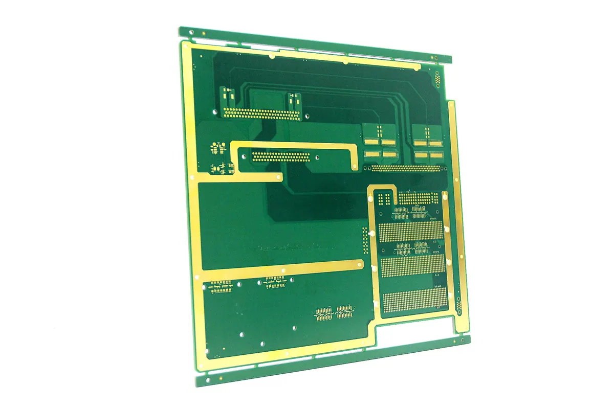
The fundamental difference between heavy copper PCB and standard FR4 PCB manufacturing lies in the etching and plating capabilities required to handle high copper weights. While standard FR4 fabrication relies on rapid, single-pass etching for thin traces (typically 0.5oz to 1oz), heavy copper production demands a multi-step plating process to build up copper thickness to 3oz, 10oz, or even higher. This shift necessitates specialized chemical baths, extended lamination cycles to manage resin flow under thick copper, and distinct etching profiles to prevent undercutting. Attempting to process heavy copper on a standard FR4 line without these adjustments results in poor trace definition, open circuits, and structural failure.
For engineers and procurement teams, recognizing these process gaps is the first step in avoiding costly redesigns. The transition from a standard 1oz core to a 10oz heavy copper layer changes the physics of the board, affecting thermal expansion, impedance control, and mechanical stress. At Omini, we see these differences play out daily in our DFM reviews, where standard design rules often fail to account for the unique constraints of high-current power layers. Understanding the specific manufacturing workflow is essential for achieving high reliability in power electronics, automotive systems, and industrial control units.
Etching Challenges and Trace Profile Control
The most visible difference in production is the etching process. In standard FR4 fabrication, the copper foil is thin, and the etching time is short. The goal is to remove the unwanted copper quickly while maintaining a vertical sidewall profile. However, when dealing with heavy copper, the volume of metal to be removed increases exponentially. If a manufacturer attempts to use standard etching parameters on a 5oz or 10oz trace, the etchant attacks the copper from the top and sides simultaneously. This leads to severe undercutting, where the trace becomes narrower at the base than at the top, or in worst-case scenarios, the trace detaches completely.
To combat this, heavy copper PCB fabrication utilizes a technique known as differential etching or reverse etching. This involves a more controlled, slower etching process that often requires specialized equipment capable of handling high-velocity spray patterns to ensure uniform removal. The chemistry of the etchant must be tightly regulated to prevent over-etching, which can destroy fine pitch features on the same board. Furthermore, the aspect ratio of the trace height to width becomes a critical constraint. As copper thickness increases, the ability to maintain tight spacing between traces diminishes. This is why heavy copper boards often have wider spacing requirements compared to their FR4 counterparts.
The impact of these etching challenges extends to the design phase. Designers must account for the etch factor, which is the ratio of copper thickness to the amount of lateral etching. In standard FR4, this factor is relatively low and predictable. In heavy copper, it varies significantly based on the specific plating thickness and the manufacturer's equipment capabilities. Ignoring this variable can lead to designs that are impossible to fabricate within the required tolerances. For a deeper dive into how these design constraints manifest in real-world production, reviewing Common Failures in Heavy Copper PCB and How to Avoid Them in the Design Stage provides critical insights into preventing these specific etching failures before the board ever hits the fab line.
Lamination and Resin Flow Dynamics
Once the inner layers are etched, the lamination process presents another major divergence between heavy copper and standard FR4 manufacturing. In a typical FR4 stackup, the prepreg (pre-impregnated fiberglass) flows easily under heat and pressure to bond the copper layers and fill the gaps between traces. The resin viscosity is optimized for thin copper, allowing it to flow rapidly and fill voids without trapping air. However, heavy copper traces act as thermal barriers and physical obstacles that impede resin flow. The high thermal mass of thick copper absorbs heat differently than the fiberglass substrate, creating temperature gradients across the panel.
If the lamination cycle is not adjusted for heavy copper, the resin may not fully flow into the gaps between the thick traces. This results in resin starvation, where voids or air pockets remain trapped under the copper. These voids are not just cosmetic; they create weak points that can lead to delamination during thermal cycling or high-power operation. To prevent this, heavy copper PCB fabrication requires extended lamination times and often higher pressures. The cycle must be long enough to allow the resin to fully penetrate the dense copper network, but not so long that the resin degrades or the copper oxidizes.
The choice of prepreg material is also more critical in heavy copper applications. Standard FR4 prepregs may not have the flow characteristics required to fill the large voids created by thick traces. Manufacturers often need to use high-flow or low-viscosity prepregs specifically designed for heavy copper stacks. Additionally, the copper foil itself may be treated differently to improve adhesion to the resin, as the mechanical stress on the bond line is significantly higher. The stackup design must be carefully engineered to balance the copper weight with the dielectric thickness to ensure structural integrity. For engineers working on complex multi-layer boards, understanding how these material choices affect performance is vital. You can explore the relationship between layer configuration and performance in our guide on PCB Stack-Up and Signal Integrity for High-Speed Boards.
Plating and Through-Hole Reliability
The plating process is perhaps the most technically demanding aspect of heavy copper PCB manufacturing. In standard FR4 production, the through-holes are plated with a thin layer of copper, typically 1mil to 1.5mil, to ensure electrical connectivity. This is achieved in a single plating cycle. For heavy copper boards, the requirement is often to have the same high copper weight on the inner layers, outer layers, and within the through-holes. This means the barrel of the hole must be plated to a much greater thickness, often 2mil or more, to handle the high current and mechanical stress.
Achieving this thickness requires a multi-step plating process. The first step is electroless copper, which provides a conductive seed layer. This is followed by a series of electrolytic copper plating cycles. Unlike standard boards, where the plating time is short, heavy copper plating requires extended immersion times to build up the necessary thickness. The challenge here is maintaining uniformity. If the plating current density is not perfectly balanced, the copper may deposit unevenly, leading to thin spots in the hole barrel that can crack under thermal stress. This is particularly problematic in high-reliability applications where thermal cycling is frequent.
Furthermore, the aspect ratio of the holes becomes a limiting factor. As the copper thickness increases, the ability to plate deep, narrow holes decreases. The plating solution must flow into the hole, and the current must distribute evenly along the barrel. In heavy copper boards, this often requires specialized plating racks and agitation systems to ensure the solution reaches the bottom of the hole. The result is a board with significantly higher mechanical strength and current carrying capacity, but at the cost of increased manufacturing complexity and time. To ensure these critical connections are sound, rigorous inspection is required. You can learn more about how advanced inspection techniques verify these connections in AOI and X-Ray Inspection in PCB Assembly.
Design for Manufacturing and Process Constraints
The production differences between heavy copper and FR4 boards fundamentally alter the Design for Manufacturing (DFM) rules. In standard FR4, designers have a wide latitude for trace widths and spacing, often down to 3-4 mils. In heavy copper, these tolerances widen significantly. A 10oz copper trace cannot be routed with 4-mil spacing; the etching process would likely short the traces or cause them to break. Designers must adhere to stricter spacing rules that account for the etch factor and the physical limitations of the plating process.
Another critical DFM consideration is the thermal relief pattern. In standard boards, thermal reliefs are used to prevent heat sinking during soldering. In heavy copper boards, the thermal mass is so high that standard thermal reliefs may not be sufficient to prevent soldering issues or may cause the pad to detach during reflow. Designers often need to use solid connections or specialized thermal relief geometries that accommodate the high heat capacity of the copper. Additionally, the placement of vias must be carefully considered. Placing a via too close to a heavy copper trace can create a stress concentration point, leading to cracking during thermal cycling.
The complexity of these constraints means that a standard DFM check is often insufficient for heavy copper projects. A specialized review is necessary to evaluate the stackup, the plating capabilities, and the etching limits. This is where the expertise of a manufacturing partner becomes invaluable. At Omini, our engineering team works closely with clients to review Gerber files and BOMs, identifying potential DFM issues before production begins. For a comprehensive guide on navigating these design challenges, refer to Common DFM Issues and How to Avoid Them in PCB Design.
Inspection and Quality Assurance Protocols
The final production stage for heavy copper PCBs involves inspection protocols that are more rigorous than those for standard FR4. Because the plating and lamination processes are more complex, the risk of hidden defects is higher. Visual inspection alone is often inadequate for verifying the quality of the through-hole plating or the integrity of the resin fill. X-ray inspection is frequently required to verify the copper thickness in the barrel and to detect voids or delamination that are not visible on the surface.
Electrical testing also presents unique challenges. The high current capacity of heavy copper traces means that standard continuity tests may not reveal subtle issues like high resistance due to thin plating. Specialized testing equipment is needed to measure the actual resistance of the traces and ensure they meet the design specifications. Furthermore, the surface finish application can be more difficult on heavy copper. The roughness of the etched copper surface can affect the adhesion of the finish, leading to potential reliability issues. Manufacturers must select surface finishes that are compatible with the thick copper profile and the intended application environment.
The cost of these additional inspection steps is a trade-off for the high reliability of the final product. In industries like automotive, aerospace, and industrial power, the cost of failure is far greater than the cost of extra inspection. By investing in thorough quality assurance, manufacturers ensure that the heavy copper PCBs will perform reliably under extreme conditions. For a detailed look at the types of defects that can occur and how to spot them, Common PCB Defects and How to Identify Them offers a practical checklist for quality control teams.
Practical Considerations for Production Planning
When planning the production of heavy copper PCBs, it is essential to factor in the extended lead times and the need for specialized equipment. Unlike standard FR4 boards, which can often be produced in a few days, heavy copper boards may require weeks of lead time due to the multiple plating cycles and longer lamination processes. This timeline must be communicated clearly to stakeholders to avoid delays in the overall project schedule. Additionally, the minimum order quantity (MOQ) for heavy copper boards is often higher, as the setup costs for the specialized equipment are significant.
Sourcing components for heavy copper assemblies also requires careful consideration. The high thermal mass of the board means that the reflow profile must be adjusted to ensure proper soldering without damaging the components. This may require a different reflow oven or a modified profile compared to standard FR4 assemblies. The thermal expansion coefficient of the heavy copper layers is also different from the substrate, which can lead to warping if not managed correctly during the assembly process. These factors highlight the importance of selecting a manufacturing partner with specific experience in heavy copper production.
Ultimately, the decision to use heavy copper over standard FR4 should be driven by the application requirements. If the design demands high current carrying capacity, low thermal resistance, or high mechanical strength, the additional manufacturing complexity is justified. However, if the application can be met with standard copper weights, sticking to FR4 can save significant time and cost. The key is to engage with the manufacturer early in the design process to ensure that the chosen technology aligns with the production capabilities and the project goals. By understanding the distinct production processes, engineers can make informed decisions that balance performance, reliability, and cost.