
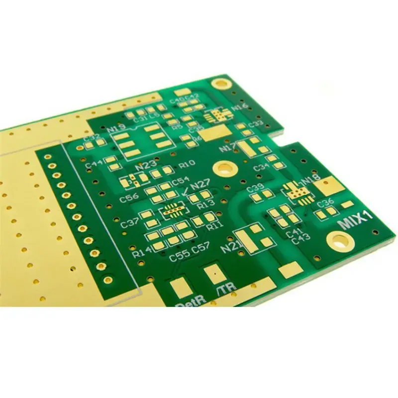
PCB Stack-Up and Signal Integrity for High-Speed Boards article image for PCB manufacturing and PCBA buyer education

Engineering Guide

PCB Stack-Up and Signal Integrity for High-Speed Boards

A PCB stack-up guide for impedance, ground planes, dielectric thickness, material selection, and high-speed manufacturing review.

Key takeaways

  • Ground planes provide low-impedance return paths for high-frequency signals.
  • Impedance depends on trace width, dielectric thickness, copper weight, and material Dk.
  • High-speed designs should confirm stack-up before routing and RFQ submission.

Direct Answer

PCB stack-up defines the copper layers, dielectric layers, ground planes, power planes, and material system. High-speed boards need stack-up review because impedance and EMI behavior depend on geometry and material values.

Manufacturing Impact

Changing prepreg thickness, copper weight, or dielectric constant changes impedance. Hardware teams should align stack-up before routing USB, Ethernet, HDMI, DDR, RF, or other controlled-impedance nets.

For the layer-count decision behind the stack-up, compare 2 Layer vs 4 Layer PCB Stackup before freezing routing density, plane strategy, and impedance assumptions.

FAQ

Why does PCB stack-up matter?

PCB stack-up controls signal return paths, impedance, EMI behavior, thermal spreading, and mechanical balance during reflow.

What files help quote impedance control?

Gerber files, stack-up notes, target impedance, material requirements, copper weight, and controlled-impedance traces help quote the build.

Related Resources