
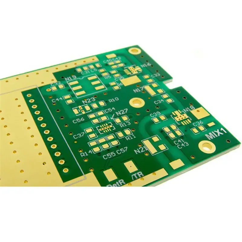
Direct Answer
High frequency PCB design presents distinct challenges that become critical above 1 GHz, where signal behavior shifts from lumped-element to wave-propagation principles. Engineers often encounter unexpected signal loss, impedance variations, and EMI issues during prototyping, even when schematics appear correct. These problems stem from parasitic effects, material limitations, and layout sensitivities that are negligible at lower frequencies but dominate in RF, microwave, and high-speed digital applications.
Overcoming these challenges requires a shift in mindset: treating traces as transmission lines, selecting materials with stable dielectric properties, and implementing disciplined grounding and shielding. Success depends on close collaboration between design and manufacturing teams to ensure that what works in simulation also survives the fabrication and assembly process.
Material Selection and Dielectric Losses
One of the first hurdles in high frequency design is material choice. Standard FR-4, while cost-effective and familiar, suffers from significant dielectric loss and inconsistent dielectric constant (Dk) above 1 GHz. This leads to signal attenuation, phase distortion, and unpredictable impedance—especially problematic in wideband or multi-channel RF systems.
Low-loss laminates such as Rogers RO4000 series, Taconic TLY, or Isola I-Tera are engineered for stable Dk and low dissipation factor (Df) across frequency. These materials reduce insertion loss and improve signal integrity, but they come with tradeoffs: higher cost, different thermal expansion coefficients, and specialized processing requirements.
During Gerber and stackup review, Omini’s engineering team validates material compatibility with the target frequency range and flags potential issues like moisture absorption or delamination risk in multilayer builds. For prototypes, we often recommend starting with a controlled impedance coupon using the actual stackup to verify performance before full panel fabrication.
Impedance Control in High Frequency Stackups
Impedance control is non-negotiable in high frequency design. Unlike low-speed circuits where trace width approximations suffice, RF and high-speed digital paths demand precise 50Ω, 75Ω, or 100Ω transmission lines with tight tolerances—often ±10% or better.
Achieving this requires a symmetrical stackup with consistent dielectric thickness, tight control over etch factors, and smooth copper profiles. Asymmetrical layer construction or uneven resin distribution can cause impedance drift, especially in microstrip and stripline configurations.
We routinely see impedance issues arise from inadequate DFM checks during the Gerber stage. That’s why we recommend early review using tools that simulate etchback and plating effects. For designs using blind/vias or HDI structures, we assess aspect ratio and fill quality to prevent signal discontinuities.
For teams looking to avoid common pitfalls, our guide on Common DFM Issues and How to Avoid Them in PCB Design covers stackup symmetry, clearance rules, and via placement—all critical for maintaining impedance in high frequency layouts.
Minimizing Signal Loss and Dispersion
Beyond impedance, signal loss becomes a dominant factor at high frequencies. Losses come from conductor resistance (skin effect), dielectric absorption, and radiation. Skin effect forces current to the surface of the trace, increasing effective resistance as frequency rises. Meanwhile, dielectric loss converts signal energy into heat, particularly in materials with high Df.
To combat this, designers should:
- Use wider traces where possible to reduce conductor loss (though this must be balanced with impedance targets).
- Select copper with lower surface roughness—rolled annealed (RA) foil outperforms electrodeposited (ED) foil at frequencies above 10 GHz.
- Choose laminates with Df below 0.004 for optimal performance in microwave bands.
Omini’s fabrication process includes profilometry checks on copper roughness and impedance coupon testing to validate loss characteristics. We also advise clients to simulate both conductor and dielectric loss in tools like HyperLynx or SIwave before finalizing the stackup.
EMI, Crosstalk, and Grounding Strategies
Electromagnetic interference and crosstalk escalate with frequency due to tighter coupling between traces and reduced wavelength. A 1 GHz signal has a wavelength of 30 cm in air—much shorter in dielectric—making even small loop areas effective antennas.
Key mitigation strategies include:
- Keeping return paths tight and continuous beneath signal traces.
- Using solid ground planes with minimal splits or slots.
- Implementing guard traces or via fencing around sensitive RF lines.
- Minimizing via inductance by using multiple vias in parallel for grounding.
Poor grounding is a frequent root cause of EMI failures in testing. We’ve seen designs where a single split ground plane under a high-speed ADC caused radiated emissions that failed compliance—fixed only by adding stitching vias and re-routing.
For high-voltage sections that may coexist with RF circuits, proper creepage and clearance are essential. Refer to our guide on PCB Creepage and Clearance Design Rules for High-Voltage Layouts to ensure safety margins don’t compromise high frequency performance.
Thermal Management in High Power RF
High frequency power amplifiers, transmitters, and radar modules generate localized heat that can shift material properties and detune circuits. Unlike general PCBs, RF power stages often require thermal vias, metal cores, or direct die attachment to manage junction temperatures.
We work with clients to optimize thermal via placement under power devices, ensuring low thermal resistance without disrupting RF ground integrity. In some cases, we recommend aluminum nitride or copper-invar-copper (CIC) substrates for extreme thermal conductivity needs.
During prototyping, we monitor for thermal drift in impedance or resonant frequency—especially in temperature-sensitive materials—and adjust the stackup or cooling strategy accordingly.
DFM, Prototyping, and Validation
No high frequency design should proceed to production without rigorous DFM review and prototype validation. Issues like undercut etching, over-plating, or laminate warpage can drastically alter high frequency behavior, yet remain invisible in standard electrical tests.
Omini’s DFM process includes:
- Impedance coupon fabrication and TDR measurement.
- Material Dk/Df verification via resonance or transmission line methods.
- Surface finish evaluation—for high frequency, ENIG or immersion silver often outperforms HASL due to smoother surfaces and lower loss.
- Assembly review for BGA voiding or tombstoning that could affect RF bonding.
We’ve seen cases where a seemingly minor change in surface finish increased insertion loss by 0.5 dB/mm at 24 GHz—enough to break a 5G link budget. Catching this in prototype saved a client weeks of redesign.
For teams preparing for prototype, our article on Common PCB Defects and How to Identify Them walks through visual and electrical checks that reveal etching inconsistencies, delamination, or plating voids that impact high frequency yield.
Heavy Copper Considerations in Hybrid Designs
Some high frequency boards combine RF sections with high-power DC circuits—think radar systems with motor drives or avionics with power converters. In these hybrid designs, heavy copper layers may be needed for current carrying, but they introduce asymmetry and etching challenges that can disrupt RF impedance.
We address this by using symmetrical heavy copper constructions or isolating power planes on dedicated layers with adequate dielectric spacing. Our guide on Common Failures in Heavy Copper PCB and How to Avoid Them in the Design Stage details how to balance current capacity with signal integrity in mixed-signal layouts.
Partnering for Manufacturable High Frequency Designs
High frequency success isn’t just about design—it’s about manufacturability. A perfect simulation means nothing if the board can’t be built reliably or varies from panel to panel. Omini acts as an extension of your engineering team, providing material guidance, stackup optimization, and process control tailored to your frequency range and performance targets.
We’ve supported clients in aerospace, telecom, and medical imaging where 24 GHz radar, 5G fronthaul, and MRI signal chains demanded extreme precision. In each case, early collaboration on Gerber files, BOM review, and prototype testing prevented costly respins and accelerated time to market.
When you’re ready to move from simulation to silicon, involve your manufacturing partner early. Share your stackup targets, frequency bands, and loss budgets. Let us help you translate RF theory into a board that performs consistently—from first article to volume production.