
Direct Answer
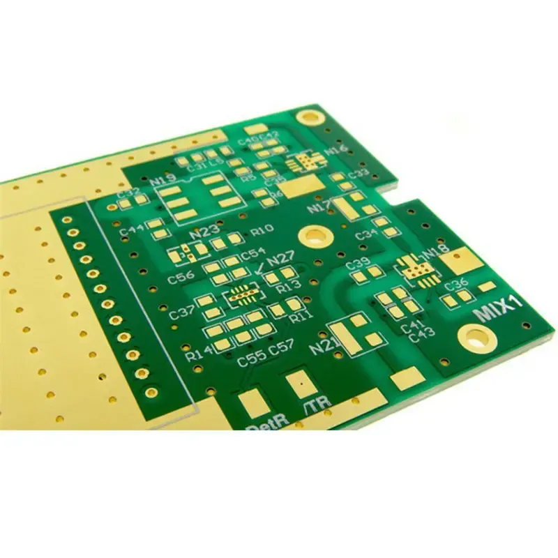
Selecting RF PCB materials starts with matching the dielectric constant (Dk) and loss tangent (Df) to your frequency, impedance, and signal integrity requirements. Unlike general-purpose FR-4, RF laminates are engineered for stable electrical properties across frequency and temperature, which is essential for maintaining controlled impedance and minimizing signal loss in high-speed and microwave circuits.
Beyond electrical performance, consider thermal conductivity, moisture absorption, and compatibility with your fabrication and assembly processes. The right material balances performance, manufacturability, and cost—especially when working with tight tolerances in microstrip, stripline, or coplanar waveguide designs.
Key Electrical Properties to Evaluate
The two most important parameters are Dk and Df. Dk determines signal propagation speed and impedance; it should be stable across your operating frequency range and temperature. Df, or dissipation factor, quantifies energy lost as heat; lower Df means less attenuation and better efficiency, particularly critical in power amplifiers, filters, and antennas.
Look for materials with tight Dk tolerance (e.g., ±0.05) and low Df (under 0.005 at 10 GHz). Also check the dissipation factor’s frequency dependence—some materials perform well at 1 GHz but degrade significantly at 20 GHz or higher.
Thermal and Environmental Stability
RF circuits often generate localized heat, especially in power stages. Thermal conductivity helps dissipate that heat, reducing hot spots that can shift Dk or cause delamination. Materials with higher thermal conductivity (e.g., >0.6 W/m·K) are advantageous in power-rich designs.
Moisture absorption is another hidden risk. Hygroscopic materials can absorb moisture during storage moisture in during storage or assembly, then release it during reflow, causing popcorning or internal delamination. Baking prepreg and laminate before use is often required—verify this with your manufacturer.
Also consider the coefficient of thermal expansion (CTE), especially in the Z-axis. A high Z-axis CTE can stress plated through-holes and vias during thermal cycling, leading to cracks or opens over time. Match the CTE of your laminate to your copper and components where possible.
Material Options by Frequency Range
For applications under 1 GHz, high-performance FR-4 variants (like Isola FR-408 or Panasonic Megtron 6) may suffice, offering better Dk stability than standard grades.
Between 1–10 GHz, reinforced hydrocarbon ceramics or glass-reinforced PTFE composites (e.g., Rogers RO4350B, RO4835, Taconic RF-35) are common choices. They offer Dk values from 3.0 to 3.5 and Df under 0.004.
Above 10 GHz, especially for 5G, radar, or satellite links, low-loss PTFE-based materials (e.g., Rogers RO3000 series, Taconic TLY-5, or Arlon AD series) are preferred. These often use ceramic fillers to stabilize Dk while maintaining very low Df (<0.002).
Some hybrid approaches use RF-grade core with standard prepreg to reduce cost—validate this with your stackup designer and manufacturer to avoid CTE mismatches.
Stackup and Design Considerations
Your material choice must align with the target impedance and stackup symmetry. Asymmetric stackups can cause warpage, especially with thicker RF cores. Use balanced layer construction and consider symmetry in both dielectric thickness and copper weight.
For microstrip and stripline, consistent Dk across the dielectric is vital. Any variation—due to material inhomogeneity or resin-rich areas—can cause impedance swings. Specify materials with tight Dk control and verify via time-domain reflectometry (TDR) during first-article inspection.
Also, consider how the material interacts with your surface finish. ENIG is often preferred for RF because it provides a smooth, flat surface. Avoid HASL on fine-pitch RF boards—the uneven solder mask can disrupt microstrip lines or cause solder balls to interfere with signal paths.
Fabrication and DFM Challenges
RF materials behave differently during processing. Some have lower copper peel strength, requiring plasma treatment or alternative bond plies to ensure adhesion. Others may be prone to etch-back or resin smear during drilling, especially if they contain woven glass or ceramic fillers.
These factors tie directly into DFM. For example, inadequate etch-back control can lead to inconsistent via plating or signal leakage between layers. Review your design with a focus on:
- Drill size and aspect ratio compatibility
- Copper clearance and annular ring minimums
- Etch-back and desmear process requirements
- Panelization stress and warpage risk
For practical guidance, review our guide on Common DFM Issues and How to Avoid Them in PCB Design to catch layout-related risks early.
Similarly, if your RF design uses heavy copper for power handling or thermal spreading, be aware of the unique risks. See Common Failures in Heavy Copper PCB and How to Avoid Them in the Design Stage for insights on delamination, cracking, and thermal stress.
Material Selection Workflow
Start by defining your electrical targets: frequency, impedance, signal loss budget, and power dissipation. Then, shortlist materials that meet Dk and Df requirements at your operating frequency.
Next, evaluate thermal and environmental specs—especially if the board will operate in harsh conditions or undergo thermal cycling. Request datasheets and, if possible, sample laminates for preliminary testing.
Engage your manufacturer early. Share your Gerber files, stackup drawing, and material preferences during DFM review. At Omini, we routinely assess material compatibility with our lamination, drilling, and plating processes to avoid surprises during production.
Finally, validate with a prototype build. Test for impedance consistency, insertion loss, and return loss across frequency. Use TDR and VNA measurements to confirm performance before committing to volume production.
Quality and Reliability Links
Material choice doesn’t end at fabrication—it affects long-term reliability. For broader context on ensuring consistency and durability, see Custom PCB Board Manufacturer: How to Ensure Quality and Reliability.
Also, understanding common failure modes helps inform material selection. For example, knowing how to spot delamination, blistering, or microcracks aids in choosing materials with better adhesion and thermal stability. Learn more in Common PCB Defects and How to Identify Them.
Practical Field Note
In RF design, material selection isn’t a one-time checklist—it’s a continuous trade-off between electrical performance, thermal behavior, and manufacturability. The best performers aren’t always the lowest-loss materials; sometimes a slightly higher Df material with better thermal conductivity and easier processing yields higher yield and lower total cost.
Always validate assumptions with your manufacturer. What looks ideal on a datasheet may need special handling in lamination, drilling, or surface finish. Bring them into the conversation early—during stackup review, not after Gerbers are frozen.
And remember: the material that works for a 24 GHz radar module may be overkill for a 2.4 GHz IoT antenna. Match the material to the application, not just the frequency band. That’s how you balance performance, reliability, and production efficiency.