
Direct Answer
PCB materials fall into several broad categories based on substrate composition, thermal properties, and intended application. The most common type is FR-4, a glass-reinforced epoxy laminate used in the majority of rigid PCBs due to its balance of cost, mechanical strength, and electrical insulation. However, material selection extends far beyond FR-4 to include high-frequency laminates, flexible substrates, metal core constructions, and hybrid systems tailored for specific performance needs. Choosing the right material is not merely a cost decision—it directly impacts signal integrity, thermal management, manufacturability, and long-term reliability. Engineers must evaluate dielectric constant, loss tangent, glass transition temperature (Tg), coefficient of thermal expansion (CTE), and moisture absorption in relation to the circuit’s operating environment and fabrication constraints.
FR-4 and Standard Rigid Substrates
FR-4 remains the dominant substrate for standard rigid PCBs, accounting for an estimated 80% of global PCB production. It consists of woven fiberglass cloth impregnated with an epoxy resin binder, providing good mechanical stability, flame resistance (UL 94 V-0 rating), and electrical insulation. Variants of FR-4 differ primarily in their glass transition temperature (Tg), with standard Tg around 130°C, mid-Tg at 150°C, and high-Tg versions reaching 170°C or higher. Higher Tg materials resist deformation during lead-free soldering processes and are preferred in automotive, industrial, and power electronics applications where thermal cycling is severe.
Beyond base FR-4, specialized rigid laminates include CEM-1 and CEM-3, which use woven glass fabric with paper or non-woven glass core layers. These are lower-cost alternatives but offer reduced mechanical and electrical performance compared to FR-4, making them suitable for simple, low-layer-count consumer electronics. For applications requiring enhanced dimensional stability or lower moisture absorption, ceramic-filled PTFE composites or hydrocarbon-based laminates may be used, though these are less common in standard rigid builds. When selecting FR-4, designers must consider not only Tg but also the resin system’s compatibility with surface finishes like ENIG or OSP, as poor adhesion can lead to delamination during assembly—a frequent DFM issue highlighted in guides on Common DFM Issues and How to Avoid Them in PCB Design.
High-Frequency and RF/Microwave Laminates
For signals operating above 1 GHz, standard FR-4 becomes inadequate due to its relatively high and frequency-dependent dielectric constant (Dk) and significant dielectric loss (Df). High-frequency laminates from manufacturers like Rogers Corporation, Taconic, and Arlon are engineered to maintain stable Dk and low Df across wide frequency ranges and temperature variations. Common Rogers series include RO3000 (ceramic-filled PTFE), RO4000 (hydrocarbon ceramic laminate), and RO4800 (loose-laminate PTFE with glass reinforcement). These materials offer Dk values ranging from 2.5 to 3.5 and dissipation factors as low as 0.001, minimizing signal attenuation and phase distortion in RF paths, antennas, and high-speed digital interfaces.
Material choice in RF design is not just about baseline Dk and Df; it also involves managing anisotropy, moisture sensitivity, and compatibility with fabrication processes. For instance, PTFE-based laminates require special surface preparation for copper adhesion, and their softness can complicate drilling and routing. Hybrid stackups, where RF layers use Rogers material while digital or power sections remain on FR-4, are increasingly common to balance performance and cost. This approach is detailed in resources on How Do I Select RF PCB Materials?, which emphasizes matching material properties to signal rise times, impedance control requirements, and thermal budget. For Omini RFQs, the useful output is a clear material callout, stackup, DFM tolerance, finish requirement, and inspection plan tied to actual factory-floor limits.
Flexible and Rigid-Flex Substrates
Flexible PCBs rely on polymer films that can withstand repeated bending without cracking or delamination. The most prevalent material is polyimide (PI), exemplified by DuPont Kapton, which offers excellent thermal stability (Tg > 300°C), chemical resistance, and mechanical durability. Polyester (PET) is a lower-cost alternative used in static flex applications where bending is minimal, such as interconnects in displays or sensors, but it lacks the thermal endurance of polyimide for soldering or dynamic flexing. Adhesiveless flex constructions, where copper is directly laminated to the polyimide film, improve flexibility and reduce thickness compared to adhesive-based systems, which can creep under stress.
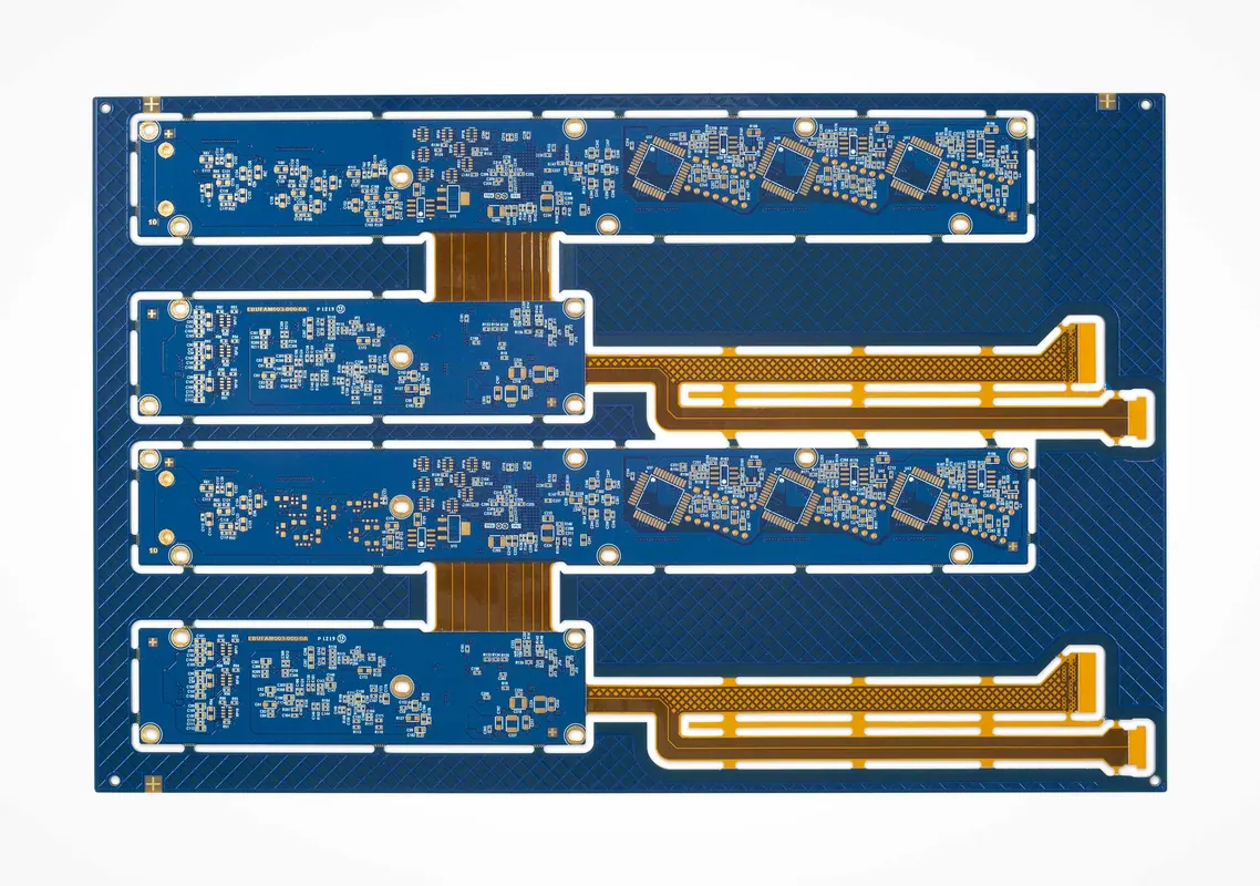
Rigid-flex PCBs combine rigid FR-4 or high-Tg sections with flexible polyimide zones to create 3D interconnect systems that eliminate connectors and reduce assembly complexity. Material compatibility between rigid and flex zones is critical—CTE mismatch can cause stress at the interface during thermal cycling, leading to cracks or delamination. Manufacturers often use flow-restricted prepregs or specialized bonding films to manage resin flow during lamination. These boards are common in medical devices, aerospace systems, and wearable electronics where space savings and reliability are paramount. Proper design includes strain relief features, controlled bend radii, and adherence to DFM rules for flex-to-rigid transitions—topics covered in discussions of Common PCB Defects and How to Identify Them to catch issues like microcracks or cover coat adhesion failures early.
Metal Core PCBs (MCPCBs)
Metal core PCBs replace the traditional dielectric substrate with a metal base layer—most commonly aluminum, but also copper or steel alloys—to provide a direct path for heat dissipation from components to a heatsink or chassis. The metal core is typically clad with a thin dielectric layer (often epoxy-based or polyimide-filled) that provides electrical isolation while allowing thermal conduction. Copper circuit traces are then etched onto this dielectric layer. Aluminum MCPCBs are widely used in LED lighting, where junction temperature directly affects luminous efficacy and lifespan, but they also serve in power converters, motor drives, and automotive ECUs where thermal management is critical.
Thermal conductivity of the dielectric layer is a key performance metric, typically ranging from 1.0 to 3.0 W/m·K for standard materials, with advanced options exceeding 5.0 W/m·K using ceramic fillers like aluminum nitride or boron nitride. However, higher thermal conductivity often comes with increased cost and potential trade-offs in dielectric strength or flexibility. MCPCBs present unique DFM challenges, such as managing thermal stress during soldering, avoiding delamination at the metal-dielectric interface, and ensuring uniform pressure during lamination. Guidance on mitigating these risks can be found in resources addressing Common Failures in Heavy Copper PCB and How to Avoid Them in the Design Stage, as heavy copper layers are frequently combined with MCPCBs in high-current power applications. When designing MCPCBs, close collaboration with a manufacturer like Omini helps optimize stackup symmetry, via design (often filled or capped), and surface finish selection to prevent oxidation or warpage.
Hybrid and Specialty Material Systems
Advanced PCB designs often require hybrid material systems that combine two or more substrates to optimize performance, cost, and manufacturability. A typical example is a multilayer board where high-speed digital or RF sections use low-loss Rogers laminates, while power distribution or analog sections remain on standard FR-4. This approach reduces material expense while meeting stringent signal integrity requirements in specific zones. Other hybrids pair FR-4 cores with polyimide flex layers for rigid-flex builds, or use ceramic-filled substrates in power modules where both thermal conductivity and electrical insulation are paramount.
Specialty materials also include halogen-free laminates (meeting IEC 61249-2-21), which substitute brominated flame retardants with phosphorus- or nitrogen-based systems to reduce toxic emissions during fire. These are increasingly mandated in European and automotive markets. Another category comprises substrates with embedded passive components—such as resistors or capacitors formed within the dielectric layer using thick-film or thin-film processes—to save space and improve high-frequency performance by reducing parasitic inductance. These technologies demand precise process control and are typically implemented in partnership with specialized EMS providers. When evaluating such options, engineers should consult comparative analyses like Comparing Different Types of Printed Circuit Board Materials to understand trade-offs in Dk, Tg, CTE, cost, and availability across material families.
Material Selection and DFM Integration
Material choice cannot be made in isolation—it must align with the entire stackup design, surface finish, assembly process, and reliability targets. For instance, a high-Tg FR-4 may be necessary for lead-free reflow, but if the resin system is incompatible with OSP finish, oxidation or poor solderability could result. Similarly, selecting a low-Df laminate for RF performance is pointless if the material absorbs moisture during storage, altering Dk and causing phase drift. Baking cycles before assembly may be required, adding complexity and risk. Thermal expansion mismatch between layers can cause via cracking or delamination during thermal cycling, especially in thick multilayer boards or those with large copper areas.
Design for Manufacturability (DFM) checks should validate material-specific constraints: minimum drill size for brittle ceramics, maximum aspect ratio for high-Tg FR-4, solder mask adhesion on polyimide, and copper balance to prevent warpage. Ignoring these factors often leads to yield loss, rework, or field failures—issues documented in failure analysis guides such as those on Common PCB Defects and How to Identify Them and Common DFM Issues and How to Avoid Them in PCB Design. Omini, as a manufacturing partner, supports material qualification through IPC-compliant testing, coupon evaluation, and process optimization to ensure that the selected substrate performs reliably from prototype to volume production. Ultimately, the best material is not the one with the highest specs on paper, but the one that satisfies electrical, thermal, mechanical, and manufacturability requirements within the project’s constraints.