
Direct Answer
Rigid PCBs account for the vast majority of printed circuit boards in production today, from consumer electronics to industrial controllers and automotive modules. The most commonly used rigid PCB materials include standard FR-4, high-Tg FR-4, halogen-free laminates, high-frequency materials like Rogers and Megtron, and thermally conductive options such as metal-core and ceramic-filled substrates. Each material serves specific electrical, thermal, and mechanical requirements, and the wrong choice at the design stage propagates into fabrication delays, assembly defects, or premature field failures.
FR-4 and Its Variants: The Workhorse Materials
Standard FR-4 dominates rigid PCB manufacturing because it delivers predictable performance at reasonable cost. The material consists of woven glass fabric impregnated with epoxy resin, creating a composite with excellent electrical insulation and mechanical stability. Most PCB fabrication houses stock multiple grades, but not all FR-4 is interchangeable.
Standard FR-4 (Tg 130-140°C)
Standard FR-4 suits single-sided through eight-layer boards for consumer, commercial, and general industrial applications. It processes well with standard drill speeds, standard desmear cycles, and conventional lamination parameters. For assemblies with one or two lead-free reflow passes and moderate operating temperatures, standard FR-4 performs adequately. However, designers pushing layer counts above ten or using thick copper should evaluate whether the lower Tg introduces risk.
High-Tg FR-4 (Tg 150-180°C)
High-Tg materials become necessary when thermal stress accumulates through multiple manufacturing steps. A typical eight-layer board with buried vias might see three or four lamination cycles, plus lead-free reflow, plus rework. Each thermal excursion drives the material closer to its glass transition point, where the resin softens and z-axis expansion accelerates. High-Tg FR-4 resists this deformation, preserving via barrel integrity and reducing pad cratering.
At Omini, we frequently see designs where standard FR-4 was specified for cost reasons, but the stackup analysis reveals thick copper planes and blind/buried via structures that warrant high-Tg material. Catching this during Gerber review prevents the delamination failures that appear after assembly or during thermal cycling test. Teams should reference Common DFM Issues and How to Avoid Them in PCB Design to align material grade with the full manufacturing path.
Halogen-Free FR-4
Halogen-free materials address regulatory and reliability concerns around brominated flame retardants. The phosphorus or nitrogen chemistries used for flame suppression behave differently during drilling and routing, often producing more resin smear that requires adjusted desmear parameters. The trade-off favors applications where ionic contamination must be minimized: medical devices, automotive sensors, and equipment deployed in humid environments. Halogen-free laminates also tend to have slightly higher moisture absorption, so storage conditions and bake-out protocols matter more than with standard FR-4.
High-Frequency and Low-Loss Materials
When signal speeds climb or frequencies enter RF territory, FR-4's dielectric properties become limiting. The dissipation factor (Df) of standard FR-4 converts signal energy into heat, attenuating edges and distorting waveforms. For these applications, specialized laminates provide controlled dielectric constants and lower loss tangents.
Rogers and PTFE-Based Laminates
Rogers RO4000 series, RO3000 series, and Taconic TLY materials use ceramic-filled thermoset resins or PTFE composites to achieve Dk values from 2.5 to 6.15 and Df values below 0.003. These materials process differently than FR-4: drill parameters must reduce fiber tear, plasma desmear often replaces chemical desmear, and thermal expansion mismatches with standard FR-4 cores complicate hybrid stackups. Mixed-material boards—where RF layers use Rogers and digital layers use FR-4—require careful attention to CTE matching and lamination pressure to prevent warpage or layer misregistration.
Megtron-6 and Nelco N4000-13
For very high-speed digital (25 Gbps and above), Megtron-6 and similar laminates offer low Dk and Df with processing characteristics closer to FR-4 than PTFE. This reduces the fabrication learning curve while improving signal integrity. These materials cost significantly more than FR-4, so designers should validate through simulation whether the performance gain justifies the expense. In many cases, optimizing trace geometry and using a well-designed PCB Stack-Up and Signal Integrity for High-Speed Boards on standard high-speed FR-4 achieves acceptable results at lower cost.
Thermally Enhanced and Metal-Core Materials
Thermal management drives material selection when components dissipate substantial heat or when ambient temperatures exceed FR-4's comfortable operating range.
Metal-Core PCBs (MCPCB)
Aluminum-core PCBs replace the bottom portion of the laminate with a metal substrate, typically aluminum for cost or copper for conductivity. The metal core conducts heat away from power components—LEDs, motor drivers, power converters—while the thin dielectric layer above maintains electrical isolation. Fabrication differs significantly from standard rigid PCBs: routing must account for metal exposure, vias cannot pass through the core (unless specialized processes are used), and the coefficient of thermal expansion (CTE) mismatch between metal and circuitry stresses solder joints during thermal cycling.
Designers specifying metal-core should engage their PCB manufacturing partner early. The dielectric thickness, thermal conductivity target, and mechanical mounting requirements all constrain material choices. Omini's production teams often review MCPCB designs for adequate creepage distance and proper thermal via placement before releasing to fabrication.
Ceramic-Filled and Thermally Conductive Laminates
For applications where metal-core is too rigid or where through-vias are required, ceramic-filled laminates like Thermagon or Bergquist materials offer thermal conductivity of 1-10 W/mK versus FR-4's 0.3 W/mK. These materials cost more and have limited color availability, but they solve thermal problems in compact enclosures where heatsinks or fans are impractical.
Material Selection in Practice: A Fabrication Perspective
Material selection cannot be divorced from the fabrication process. A designer might specify Rogers 4350B for its electrical properties, but if the chosen fabricator lacks experience with the material's prepreg flow characteristics, the result may be resin starvation or excessive dielectric thickness untrim. Similarly, heavy copper designs on standard FR-4 frequently encounter Common Failures in Heavy Copper PCB and How to Avoid Them in the Design Stage, where thermal stress from thick copper overwhelms the base material.
The Gerber-to-Material Validation Path
Before any material is ordered, the fabrication house should validate the design data against material capabilities. Key checks include:
- Layer count and aspect ratio: High aspect ratio plated through-holes need higher resin content and adjusted drill parameters
- Copper weight distribution: Uneven copper distribution across layers creates lamination pressure variations that high-Tg materials handle better
- Minimum dielectric spacing: High-voltage designs need adequate prepreg thickness, which constrains material choices
- Impedance control requirements: Tight impedance tolerances may mandate specific prepreg styles or low-Dk cores
These checks feed into the DFM report that precedes tooling. Teams working on complex rigid-flex designs should also review Rigid-Flex PCB DFM Tips Before PCB Manufacturing to understand how rigid material choices interface with flex sections.
Surface Finish and Material Compatibility
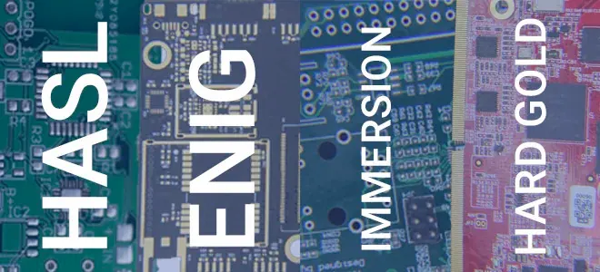
The surface finish selection interacts with base material. ENIG (electroless nickel immersion gold) works universally but adds cost. OSP (organic solderability preservative) demands flatter surfaces and shorter assembly windows. HASL (hot air solder leveling) stresses thin cores and fine-pitch features with its thermal shock. For high-Tg or high-frequency materials, the finish must not introduce contamination that affects RF performance or solder joint reliability.
Inspection and Reliability Considerations
Material properties directly impact which inspection methods are effective and what failure modes dominate. Standard optical inspection catches surface defects, but internal defects—delamination, resin voids, conductive anodic filament (CAF) growth—require different approaches.
Cross-sectional analysis and microsectioning verify via barrel quality and laminate integrity. For high-reliability applications, this destructive testing validates that the selected material performed as expected through the full thermal profile. AOI and X-Ray Inspection in PCB Assembly provides additional quality coverage for assembled boards, catching solder defects and component placement issues that material choice alone cannot prevent.
CAF resistance varies significantly by material grade. Standard FR-4 with high glass content and poor resin wetting is more susceptible to CAF growth between biased conductors in humid conditions. High-Tg and halogen-free formulations generally improve CAF resistance, but the improvement must be validated against the specific resin system and glass style used.
Practical Guidance for Material Specification
Specifying rigid PCB materials requires balancing electrical requirements, thermal environment, mechanical constraints, and cost. The following framework helps narrow choices without over-specifying:
1. Start with operating temperature and thermal cycles: If T-operating plus self-heating exceeds 100°C, or if the assembly sees more than three lead-free reflows, default to high-Tg 2. Evaluate signal speed and frequency: Below 1 GHz with relaxed loss budgets, standard or high-speed FR-4 suffices; above this, simulate with candidate laminates 3. Assess thermal dissipation needs: Calculate thermal resistance path; if junction temperatures exceed ratings with FR-4, evaluate metal-core or ceramic-filled options 4. Consider environmental and regulatory constraints: Automotive, medical, and aerospace applications may mandate halogen-free or specific flame ratings 5. Validate with fabrication partner: Confirm material availability, processing experience, and any design rule adjustments needed
At Omini, material review is integrated into our DFM process for both prototype and volume PCB fabrication. Catching mismatches between specified material and actual manufacturing stress saves weeks in respin cycles and prevents the subtle failures that escape initial testing only to surface in the field.
The landscape of rigid PCB materials continues to evolve with demands for higher speed, greater miniaturization, and harsher operating environments. FR-4 in its variants will remain the default choice for most applications, but the margins where specialized materials matter are expanding. Engineers who understand when to step beyond standard specifications—and who engage their manufacturing partners early in that decision—build more reliable products with fewer production surprises.