
Direct Answer
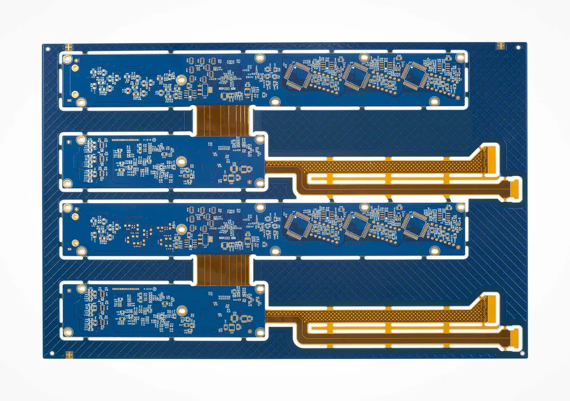
Rigid-flex PCB DFM should start before Gerber release because the flex-to-rigid transition is the highest-risk mechanical area. Bend radius, coverlay, adhesive, via location, and copper shape affect yield during lamination, reflow, and final assembly.
For quick-turn builds, use the Rigid-Flex PCB Prototype Readiness Checklist before requesting prototype pricing so bend drawings, stackup transitions, stiffeners, fixture needs, and inspection scope are visible in the RFQ package.
Manufacturing Checks
Static bend regions should use at least 5x flex thickness as a practical starting point. Dynamic bend regions should use at least 10x flex thickness because repeated motion increases copper fatigue risk.
Vias should stay out of bend zones by at least 50 mil when layout space allows. Teardrops, curved traces, and staggered top-bottom conductors reduce cracking and the I-beam stiffness effect.