
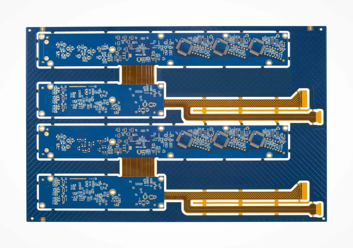
Direct Answer
A rigid-flex PCB prototype is ready for quick-turn review only when the mechanical bend intent, rigid-to-flex stackup transition, coverlay and stiffener requirements, assembly support, and inspection scope are defined before fabrication release.
Engineering Context
Capability page for prototype rigid-flex builds where mechanical design, fabrication rules, assembly handling, and reliability evidence interact. The goal is to decide whether the design package is ready for quote or still needs DFM closure.
Current taxonomy dimensions: pcbCategory: rigid-flex, leadTime: quick-turn-prototype, quantity: prototype.
Rigid-Flex PCB Prototype is useful only when it changes the engineering or sourcing review. The page should make clear what the buyer must decide before quote, what the manufacturer can verify from the supplied package, and which assumptions would create rework if they are discovered after fabrication or assembly starts.
The key decision is: Prototype rigid-flex PCBs without creating bend-zone, stackup-transition, and assembly-support failures. A good RFQ connects that decision to concrete constraints, required handoff files, inspection scope, sourcing boundaries, and test evidence. If a requirement changes stackup, BOM control, fixture access, inspection depth, or shipment documentation, it belongs in the quote package rather than in a late email thread.
The relevant dimensions are pcbCategory: rigid-flex, leadTime: quick-turn-prototype, quantity: prototype. Each dimension should affect the quote inputs, manufacturing risks, or quality checks. A material, platform, industry, or capability label is not enough by itself unless it changes the actual review path.
Source-Backed Review Notes
- Rigid-flex design source boundary - IPC-2223F sectional design standard for flexible and rigid-flexible printed boards (standard).
Source fact: IPC-2223F is the sectional design standard boundary for flexible and rigid-flexible printed boards and interconnecting structures. Omini interpretation: Use this to require bend-zone, stackup-transition, coverlay, stiffener, and flex-material assumptions before prototype quote; do not convert it into copied numeric limits. Allowed usage: Use on rigid-flex, flex PCB, prototype readiness, stackup transition, and manufacturing DFM pages.
- Rigid-flex performance source boundary - IPC-6013E qualification and performance specification for flexible and rigid-flex printed boards (standard).
Source fact: IPC-6013E is the qualification and performance specification boundary for flexible printed boards, including rigid-flex constructions. Omini interpretation: Use this to separate design readiness from performance and acceptance documentation; a prototype RFQ should name required class, inspection, and reliability evidence when they matter. Allowed usage: Use on rigid-flex, flex PCB, reliability, inspection, and prototype-to-production readiness pages.
- High-reliability PCB QA process boundary - NASA GSFC-STD-8001 printed wiring board quality assurance (government).
Source fact: NASA GSFC-STD-8001 defines PCB design, procurement, production, quality verification, and use requirements for GSFC mission hardware. Omini interpretation: Use this as conservative QA process framing when prototype choices affect reliability; do not imply NASA approval or apply mission-hardware requirements to commercial builds. Allowed usage: Use on reliability, prototype review, inspection planning, and high-reliability PCB manufacturing pages.
- Existing OminiPCB repository content (internal): May seed structure and internal links; engineering claims still need external verification when specifications are involved.
Manufacturing Constraints
- define each static or dynamic bend zone, bend direction, bend count expectation, and keepout intent in the drawing package
- keep vias, pads, component bodies, abrupt trace-width changes, and copper pours out of bend areas unless the fabricator explicitly reviews the exception
- document rigid-to-flex transitions, coverlay openings, stiffeners, adhesive boundaries, and finished flex thickness targets
- show where impedance-controlled traces cross rigid and flex sections so stackup changes are reviewed before quote
- make panel, carrier, or fixture assumptions visible when thin flex sections must survive SMT, inspection, programming, or functional test
- copper cracking or insulation damage when bend zones are treated like ordinary routing area
- delamination or resin recession near rigid-to-flex transition zones
- coverlay registration problems around pads, openings, and stiffener edges
- assembly stress when rigid islands or thin flex tails are not supported during SMT handling
- prototype lead time expanding after stackup, material, or fixture review exposes missing assumptions
- inspection gaps when hidden transition-zone defects, plated holes, or solder joints are not matched to a defined check
Prototype Readiness Criteria
- release-ready: bend drawing names static versus dynamic flex areas, bend direction, and installation or operating flex expectation
- release-ready: stackup separates rigid and flex sections and states target finished thickness, copper weight, coverlay, stiffener, and adhesive assumptions
- release-ready: transition zones avoid vias, sharp copper changes, unsupported pads, and component bodies unless the exception is called out for DFM review
- not ready: the RFQ only says rigid-flex prototype without mechanical drawings, flex constraints, or assembly handling assumptions
- not ready: quick turn depends on unresolved impedance, unsupported flex tails, missing fixture plan, or unspecified acceptance evidence
Quote Inputs
- Gerber or ODB++ plus drill files and fabrication drawing
- stackup drawing that separates rigid sections, flex sections, coverlay, adhesive, stiffeners, and finished thickness targets
- bend drawing with bend direction, static or dynamic flex intent, and keepout regions
- stiffener material, thickness, location, and connector or component support reason
- assembly drawing, BOM, centroid, polarity notes, and any programmed-device or functional-test requirements
- panel, carrier, fixture, or handling assumptions for SMT, AOI, X-ray, programming, and shipment
- controlled impedance, differential pair, RF, or high-speed constraints when traces cross rigid and flex sections
- inspection and acceptance evidence needed for the prototype stage versus later production qualification
Inspection And Build Plan
- DFM review for bend zones, transition geometry, coverlay openings, stiffeners, and manufacturable flex thickness
- stackup and material review before quick-turn commitment because rigid-flex assumptions can change lamination flow and lead time
- AOI for visible SMT placement and solder-joint checks on supported rigid areas
- X-ray or cross-section discussion when hidden joints, plated holes, transition zones, or reliability evidence justify destructive or non-destructive review
- functional or continuity test planning when flex tails, connectors, programming pads, or strain-relief assumptions affect the prototype
Example Review
A wearable sensor prototype with two rigid islands and one flex tail is not ready just because the Gerbers export cleanly. The review should confirm bend direction, static versus dynamic flex intent, via and copper keepouts, coverlay opening size, stiffener material and edge location, connector strain relief, finished flex thickness, and whether SMT assembly needs a carrier. If the flex tail also carries impedance-controlled sensor signals, the stackup and reference path must be reviewed before quick-turn lead time is promised.
Pre-Quote Review
Before requesting Rigid-Flex PCB Prototype, compare the design against adjacent options in the same cluster. If another material, platform, finish, or assembly route would use the same quote inputs and risk controls, the project may not need a separate sourcing path.
Source-backed notes should be used as engineering boundaries, not as copied datasheet text, standards excerpts, legal advice, or unsupported certification claims. The RFQ should describe the real product, operating environment, files, and acceptance checks that the manufacturer can verify.
The final quote package should make responsibility clear: design intent and acceptance criteria come from the buyer; DFM, fabrication, assembly, inspection, sourcing feedback, and delivery feasibility come from the manufacturing review.
Tradeoffs
- Rigid-flex can reduce connectors, cable assemblies, and enclosure volume, but it moves risk into early mechanical and stackup review.
- Quick prototypes are possible only after mechanical assumptions, material stackup, and assembly support are visible enough for DFM.
- A lower-cost rigid PCB plus cable may be safer for early proof-of-concept builds when the enclosure geometry is still changing.
- A rigid-flex prototype is worth a separate sourcing path only when it changes bend-zone rules, transition design, fixture needs, inspection evidence, or reliability expectations.
- The first prototype should prove manufacturability and handling assumptions before the team treats the design as a production cost baseline.
CTA
Request a PCB quote when Gerber, stackup, BOM, quantity, lead time, and inspection requirements are ready for review.