
Direct Answer
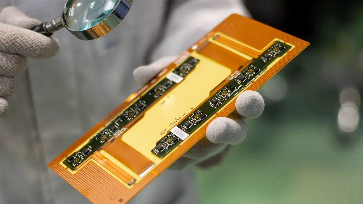
Flex PCB materials are engineered for applications requiring bending, folding, or conformal mounting where rigid boards fail. The core construction typically uses a polyimide substrate laminated with copper foil, often protected by a coverlay or cover film. This stackup allows the circuit to flex repeatedly without cracking traces or delaminating, making it essential in wearables, medical devices, aerospace connectors, and dynamic robotics.
Classification depends on layer count, flexibility demands, and mechanical stress. Single-sided flex is simplest, used for static bends like display connectors. Double-sided adds plated through-hots for more complex routing. Multilayer flex supports high-density interconnects, while rigid-flex combines flexible sections with rigid boards for 3D packaging. Material choice — especially dielectric thickness, copper type (ED or RA), and adhesive vs. adhesive-less systems — directly impacts bend radius, signal loss, and long-term reliability.
Material Construction of Flex PCBs
The foundation of any flex PCB is the dielectric base, most commonly polyimide (PI) for its balance of flexibility, thermal resistance (up to 400°C), and chemical stability. Alternative substrates like polyester (PET) or liquid crystal polymer (LCP) are used in lower-cost or high-frequency applications, respectively. Copper foil is bonded to this base using either adhesive or adhesive-less methods. Adhesive-less laminates, where copper is directly cast onto the polyimide, offer better thermal conductivity, thinner profiles, and improved dynamic flex performance.
Copper selection matters: electro-deposited (ED) copper is cheaper and smoother for static flex, while rolled-annealed (RA) copper provides superior ductility and fatigue resistance for dynamic flexing. Coverlays — typically polyimide with adhesive — protect the outer copper layers, replacing solder mask in flexible zones. Stiffeners made of FR-4, polyimide, or stainless steel are added in connector areas or under components to prevent bending stress on solder joints.
In production, Omini reviews Gerber files and stackup specs during DFM to ensure material compatibility with bending requirements, especially in rigid-flex transitions where CTE mismatch can cause delamination. Proper material pairing prevents issues like copper cracking or coverlay lifting during thermal cycling.
Classification by Flexibility and Use Case
Flex PCBs are categorized not just by layers, but by how they will be used in the product lifecycle. Static flex applications involve one-time or infrequent bending — such as folding a circuit during device assembly — where cost-effective materials like adhesive-based polyimide and ED copper suffice. These are common in consumer electronics for cable replacements or internal interconnects.
Dynamic flex, however, requires the circuit to bend repeatedly during operation, as in print heads, hinged laptop screens, or robotic arms. Here, material fatigue becomes critical. Designers specify RA copper, adhesive-less substrates, and minimized via density in bend zones. Bend radius is calculated based on material thickness and copper ductility; violating it leads to trace fatigue and open circuits over time.
Multilayer flex adds complexity: inner layers must withstand the same bending stresses, so designers often route critical signals away from the bend axis and use ground planes for shielding. Rigid-flex designs take this further by integrating rigid sections (for component mounting) with flexible interconnects, reducing connectors and improving shock resistance. Omini’s engineering team evaluates these tradeoffs during prototyping, balancing layer count, bend life, and assembly yield.
Advantages Over Rigid PCBs in Key Applications
The primary advantage of flex PCBs is their ability to replace bulky wire harnesses and rigid boards with a lightweight, space-efficient interconnect that conforms to 3D geometries. This reduces assembly time, eliminates solder joints prone to vibration failure, and enables thinner, more ergonomic devices. In medical implants or wearable sensors, flex PCBs allow the circuit to move with the body without inducing stress.
Thermal management is another benefit. Polyimide substrates dissipate heat better than FR-4 in thin profiles, and the ability to route heat-generating components near flexible zones allows for localized cooling strategies. In high-vibration environments like automotive sensors or aerospace avionics, flex PCBs outperform rigid boards by absorbing mechanical stress that would otherwise crack solder joints or fracture substrates.
From a manufacturing standpoint, flex PCBs simplify box build. Instead of routing multiple cables and connectors, a single flex circuit can interconnect boards, reducing BOM complexity and assembly errors. Omini’s EMS team often integrates flex circuits into box-build projects, where DFM checks ensure proper strain relief, connector alignment, and solder joint protection during final assembly.
Material Impact on Signal Integrity and High-Speed Design
While flex PCBs excel mechanically, their electrical performance requires attention, especially above 1 GHz. The dielectric constant (Dk) of polyimide (~3.4) is higher than some low-loss laminates, which can increase signal propagation delay and affect impedance control. For high-speed flex, designers may opt for LCP-based substrates (Dk ~2.9) or use microstrip/stripline configurations with careful trace width/spacing tuning.
Adhesive layers in traditional flex stackups can introduce signal loss and uneven surfaces, impacting high-frequency performance. Adhesive-less constructions mitigate this by providing a smoother copper interface and lower loss tangent. Omini’s stackup review includes impedance modeling for flex sections, particularly in rigid-flex designs where signal transitions between rigid and flexible zones must maintain continuity.
Via design also matters: plated through-holes in flex zones can create stress concentrators. Via-in-pad or staggered vias are avoided in bend areas; instead, vias are placed in rigidized sections or replaced with surface-mounted connectors when possible. For prototyping, Omini performs coupon testing on flex samples to validate bend life and electrical continuity after thermal-mechanical cycling.
Practical Considerations for Prototyping and Production
When prototyping flex PCBs, early collaboration on material specs prevents costly redesigns. Gerber files must clearly define bend zones, stiffener locations, and coverlay openings. BOM notes should specify copper type (RA vs. ED), substrate grade, and any required certifications (e.g., IPC-6013, MIL-PRF-31032). Omini’s DFM process includes checking for acute angles in bend zones, insufficient coverlay overlap, and via placement near flex boundaries.
During SMT assembly, flex panels often require fixtureing to maintain flatness. Unlike rigid boards, flex circuits can drift under squeegee pressure, causing misalignment. Low-tack adhesives or vacuum tables are used, and component placement is adjusted for flex-induced distortion. Omini’s assembly engineers adjust pick-and-place programs and reflow profiles to accommodate flex panel behavior, especially when mounting BGAs or QFNs near flex edges.
Inspection methods adapt too. AOI systems may need angled lighting to capture flex contours, and X-ray inspection helps verify hidden solder joints under stiffeners or in multilayer sections. For high-reliability applications, Omini recommends coupon-level bend testing and IPC-TM-650 thermal cycling validation as part of the quality plan.
Ultimately, flex PCB success hinges on matching material properties to mechanical and electrical demands. Whether replacing a cable assembly in a drone gimbal or enabling a foldable smartphone display, the right stackup — guided by DFM, material science, and production expertise — ensures the circuit bends without breaking.
Related Omini Engineering Notes
- Double Sided PCB: Advantages, Applications, and Manufacturing Process
- Flex PCB Manufacturing Process: Materials Selection, Etching, & Lamination
- Rigid-Flex PCB DFM Tips Before PCB Manufacturing
- PCB Stack-Up and Signal Integrity for High-Speed Boards
- AOI and X-Ray Inspection in PCB Assembly