
Direct Answer
SMT assembly risk rises when an EMS's manufacturing capacity is overcommitted or its process automation lags behind industry trends. You must evaluate the number of SMT lines, inspection coverage, and traceability systems—not just price or lead time—to avoid hidden defects, delayed deliveries, and costly rework in your PCBA production.
---
Why Capacity and EMS Trends Are the Real Risk Drivers
Most engineers evaluate an EMS partner by quoting price per placement and promised lead time. Those two numbers hide the actual risk. A low quote often means the EMS is running lines at high utilization with minimal inspection, or it is using older placement machines that cannot handle fine-pitch components reliably. The EMS trend toward higher automation—100% AOI, automated solder paste inspection (SPI), and real-time traceability—directly reduces the probability that defects escape to your final product.
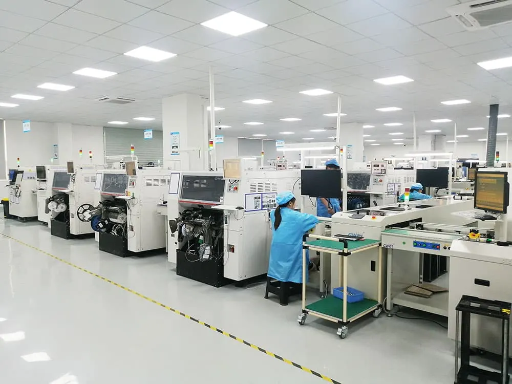
Capacity is not square meters of factory floor. It is the number of SMT lines, the placement speed per line, the available inspection resources, and the buffer for rework or demand spikes. If an EMS runs three shifts at 95% utilization, any component delay or line failure pushes your delivery date. If the same EMS has 20% idle capacity, it can absorb disruptions without impacting your schedule.
The EMS trend in process control matters just as much. A partner that has invested in automated inspection on every board, not just sample lots, will catch solder defects before they become field failures. A partner that still relies on manual visual inspection for BGA packages is a higher risk, regardless of how cheap their quote looks.
---
How to Read an EMS Capacity Profile
Before you place an order, request a capacity profile that goes beyond total output. You need specific data about the lines that will run your board.
What a Capacity Profile Must Include
| Capacity Element | What to Ask For | Why It Matters |
|---|---|---|
| SMT line count | Number of lines, not total factory size | Determines parallel production and changeover frequency |
| Placement speed | CPH (components per hour) per line | Tells you if the line can handle your board's component count |
| Mounter mix | Chipshooters vs. flexible mounters | Fine-pitch QFPs and BGAs need flexible mounters with higher accuracy |
| Inspection resources | Number of SPI, AOI, and X-ray machines | Determines whether 100% inspection is physically possible |
| Shift plan | Number of shifts and days per week | Reveals utilization and buffer for urgent orders |
| Utilization rate | Current percentage of line capacity used | High utilization means low buffer for disruptions |
| Rework capacity | Dedicated rework stations and skilled operators | Critical for BGA rework and field return repair |
A practical example: your board has 1,200 components, mostly 0402 passives and one 0.8 mm pitch BGA. A line with a chipshooter rated at 60,000 CPH and a flexible mounter rated at 15,000 CPH can place your board in roughly 90 seconds of placement time. If the EMS quotes a line with only a chipshooter and no flexible mounter, the BGA placement accuracy is at risk. Ask which specific line will run your product.
The Utilization Trap
High utilization is not inherently bad. An EMS running at 85% utilization with strong process controls may be more reliable than one at 60% utilization with weak inspection. The risk comes from hidden overcommitment. Ask for the utilization rate on the specific line that will run your board, not the factory average. A line dedicated to high-volume consumer products may be at 95% utilization, while a high-mix line for industrial boards sits at 70%. Your board's risk profile depends on which line it lands on.
---
EMS Automation Trends That Reduce Defect Risk
The EMS industry has shifted toward automated inspection and data collection. These trends are not marketing buzzwords; they change your defect risk profile.
100% AOI and SPI Coverage
The most significant risk-reduction trend is moving from sample-based inspection to 100% automated inspection. SPI checks solder paste volume, height, and area after printing. AOI checks component placement, polarity, and solder joint quality after reflow. When an EMS runs SPI and AOI on every board, defects like tombstoning, insufficient solder, and misaligned components are caught immediately.
Without 100% SPI, a stencil clog or paste starvation issue can run for an entire shift before anyone notices. That means hundreds of boards with insufficient solder on a QFP or BGA. The cost of rework on those boards far exceeds the cost of the inspection equipment.
X-Ray for Hidden Joints
BGA and QFN packages have solder joints under the component body. AOI cannot see them. X-ray inspection is the only way to verify solder joint integrity for these packages. Ask whether the EMS has X-ray capability and whether it is used on every BGA board or only on first articles. If X-ray is only used for initial qualification, you accept the risk of voiding, bridging, or open joints on every subsequent board.
Real-Time Traceability
Modern EMS trends include recording solder paste lot numbers, reflow oven profiles, and AOI results per board. This traceability is essential for root-cause analysis. If a field failure appears six months after delivery, you need to know which solder paste lot, which reflow profile, and which AOI results correspond to that board. Without this data, you cannot determine whether the failure is a process issue, a component issue, or a design issue.
For a deeper look at how thermal processing and advanced packaging trends affect SMT risk, see How to Evaluate SMT Assembly Risk from FOPLP and Thermal Processing Trends.
---
What to Put in Your RFQ to Force Process Commitments
Your RFQ is the tool that forces an EMS to commit to specific process controls. If you do not specify inspection coverage and handling requirements, the EMS will default to its minimum standard, which may not match your risk tolerance.
Required RFQ Elements
- Expected annual volume and order frequency: This tells the EMS how much line capacity to reserve and how often changeovers will occur.
- Number of SMT lines required: If your volume needs two lines running in parallel, say so. The EMS must commit to that capacity.
- Inspection coverage: Specify 100% SPI and 100% AOI on all boards. For BGA and QFN packages, specify X-ray inspection on a defined sample rate or 100% if your reliability requirements demand it.
- Reflow profile window: Provide the recommended reflow profile from your component datasheets, especially for BGAs and other temperature-sensitive packages. Ask the EMS to confirm their oven can hold the required peak temperature and time above liquidus within your specified window.
- MSD handling per J-STD-033: If your BOM includes moisture-sensitive devices, specify the required baking and floor-life management. J-STD-033 defines the handling, packing, and baking procedures for moisture-sensitive components.
- Acceptable lead time: Give both a target and a maximum. This forces the EMS to state whether your volume fits their current capacity.
- Capacity plan for your product: Ask how many shifts they can run for your order and what happens if a key component goes on allocation.
The Stencil Design Connection
Stencil design directly affects solder paste deposition quality. Your RFQ should specify stencil aperture ratios, thickness, and any step-stencil requirements for mixed-technology boards. If your board has both 0402 passives and a 0.5 mm pitch QFP, a single-thickness stencil may not provide adequate paste release for both. The EMS's stencil design capability and their trend toward laser-cut stencils with nano-coating affect your solder defect risk. For more on this topic, see How to Evaluate SMT Assembly Risk from Manufacturing Capacity and Stencil Trends.
---
A Practical Scoring Matrix for Comparing EMS Partners
When you evaluate multiple EMS partners, use a structured scoring matrix. This removes subjective bias and forces you to weigh capacity and automation trends objectively.
| Criterion | Weight | EMS A Score (1-5) | EMS B Score (1-5) | EMS C Score (1-5) |
|---|---|---|---|---|
| Number of SMT lines available for your product | 15% | 4 | 3 | 5 |
| Placement accuracy for fine-pitch components | 15% | 5 | 4 | 3 |
| 100% SPI and AOI coverage | 20% | 5 | 3 | 4 |
| X-ray inspection for BGA/QFN | 10% | 4 | 2 | 5 |
| Real-time traceability (paste lot, reflow profile, AOI data) | 15% | 5 | 3 | 4 |
| Utilization rate and buffer capacity | 10% | 3 | 4 | 4 |
| Rework capability and response time | 10% | 4 | 4 | 3 |
| MSD handling per J-STD-033 | 5% | 5 | 4 | 4 |
| Weighted Total | 100% | 4.55 | 3.35 | 4.00 |
In this example, EMS A scores highest because of its 100% inspection coverage and traceability, even though EMS C has more lines. The weighted total reflects that inspection and traceability reduce defect risk more than raw capacity.
> Practical note: Weight the criteria based on your product's risk profile. A high-reliability medical device should weight X-ray and traceability higher. A consumer product with tight cost targets might weight line capacity and utilization higher. There is no universal matrix.
---
Common Mistakes When Evaluating SMT Assembly Risk
Engineers repeat the same mistakes when assessing EMS capacity and trends. Recognizing these patterns helps you avoid them.
Mistake 1: Treating Capacity as a Single Number
Total factory square footage or annual output tells you nothing about your specific board. A factory with 20 SMT lines may have only two lines capable of handling your 0.4 mm pitch BGA. Ask which lines can run your board and what their current utilization is.
Mistake 2: Ignoring Changeover Frequency
High-mix low-volume boards require frequent changeovers. Each changeover introduces risk of setup errors: wrong feeder, wrong component reel, or incorrect stencil. An EMS with dedicated lines for high-mix work has optimized changeover procedures. An EMS that runs high-volume production on the same lines may rush changeovers, increasing setup error risk.
Mistake 3: Assuming AOI Means 100% Coverage
Some EMS providers have AOI machines but use them only for first-article inspection or random sampling. Ask specifically: "Is AOI run on every board that comes off the line?" If the answer is no, ask what sample rate they use and how they decide which boards get inspected.
Mistake 4: Overlooking MSD Handling
Moisture-sensitive devices absorb humidity from the air. If they are not baked before reflow, the trapped moisture expands and causes package cracking, delamination, or "popcorn" damage. J-STD-033 defines the handling procedures, but not all EMS providers follow them rigorously. Ask how they track floor life for MSD components and whether they bake components that exceed their floor life.
Mistake 5: Not Checking Traceability Depth
Traceability is not just a barcode on the box. It is the ability to link a specific board to its solder paste lot, reflow profile, AOI images, and component lot numbers. Ask the EMS to show you a sample traceability report from a recent production run. If they cannot produce one, your root-cause analysis capability after a field failure is severely limited.
For a broader view of how market and sales trends affect your sourcing decisions, see How to Evaluate SMT Assembly Risk from Sales and Electronics Trends.
---
When to Involve the Manufacturer Early
Do not wait until the RFQ stage to discuss capacity and process controls. Involve the EMS during your design review, especially for boards with challenging assembly requirements.
Early Involvement Scenarios
- Fine-pitch components below 0.5 mm pitch: Your land pattern design per IPC-7351 must match the EMS's placement capability. Early discussion confirms whether their flexible mounters can handle the accuracy requirement.
- Mixed-technology boards: Through-hole and SMT components on the same board require specific process sequencing. The EMS can advise on stencil design and whether selective soldering or hand soldering is needed.
- High-layer-count PCBs with thick copper: A 12-layer board with 2 oz copper on all layers has different thermal behavior during reflow than a standard 4-layer board. The EMS's reflow oven must handle the thermal mass. Early discussion prevents reflow profile issues later.
When you involve the EMS early, you also get feedback on your BOM. They can flag components that are difficult to source or that have long lead times. This connects directly to inventory and sourcing risk. See How to Evaluate SMT Assembly Risk from Inventory and Sourcing Trends for a deeper discussion.
---
The Connection Between PCB Manufacturing and Assembly Risk
Your PCB supplier and your EMS are not independent. The PCB's surface finish, solder mask, and flatness directly affect SMT assembly yield. A PCB with ENIG finish and good solder mask registration will have better solder wetting than a board with HASL finish and poor mask alignment.
When you evaluate SMT assembly risk, include your PCB supplier in the assessment. Ask whether the PCB's copper weight, surface finish, and solder mask are compatible with the EMS's reflow process. A board with 1 oz copper and OSP finish behaves differently during reflow than a board with 2 oz copper and ENIG. The EMS's reflow profile must be adjusted accordingly.
For a full treatment of how PCB manufacturing and sourcing decisions affect SMT risk, see How to Evaluate SMT Assembly Risk from PCB Manufacturing and Sourcing Trends.
---
FAQ
Q: Why does manufacturing capacity and EMS trend evaluation matter for SMT assembly risk?
A: Manufacturing capacity determines how many SMT lines can run your PCBA in parallel and how much buffer exists for rework or sudden demand spikes. EMS trends such as line automation, AOI coverage, and real-time traceability directly affect your risk of delayed deliveries, hidden defects, and costly rework. Evaluating these factors before placing an order helps you avoid selecting a partner whose capacity is already overcommitted or whose process controls are outdated.
Q: Where do engineers make mistakes when evaluating SMT assembly risk?
A: The most common mistake is treating capacity as a single number, like total square meters of factory space, instead of looking at the number of SMT lines, the mix of chipshooters and flexible mounters, and the available AOI/X-ray inspection capacity. Engineers also overlook whether the EMS has dedicated lines for high-mix low-volume jobs versus high-volume production, which changes changeover frequency and risk of setup errors. Another frequent error is ignoring the EMS's trend in automation, such as whether they use automated SPI and AOI on every board, not just on sample lots.
Q: How can I verify an EMS's capacity and process trends before ordering?
A: Before committing to a PCBA assembly partner, request a capacity profile that lists the number of SMT lines, the placement speed per line, the available SPI/AOI/X-ray machines, and the planned weekly output for your product. Ask for their current utilization rate and how they handle urgent rework or line failures. Also review their EMS trend in digital traceability, such as whether they record solder paste lot numbers, reflow oven profiles, and AOI results per board, because that data is critical for root-cause analysis if field failures appear.
Q: What capacity and EMS trend information should I include in an RFQ for PCBA assembly?
A: In your RFQ, include the expected annual volume, the number of SMT assembly lines you require, the required inspection coverage (e.g., 100% AOI on all boards), and the acceptable lead time for both prototypes and production. Specify the reflow profile window for your BGA packages and any moisture-sensitive device handling requirements per J-STD-033. Also ask for their capacity plan for your product, including how many shifts they can run and what happens if a key component goes on allocation.
Q: How does stencil design affect SMT assembly risk?
A: Stencil aperture size, thickness, and wall finish determine how much solder paste is deposited on each pad. If the stencil is too thick for fine-pitch components, you get solder bridging. If it is too thin for large ground pads, you get insufficient solder and potential open joints. A step-stencil with different thicknesses for different component types is often required for mixed-technology boards. The EMS's stencil design capability and their use of laser-cut stencils with nano-coating directly affect paste release and defect rates.
Q: What is the difference between AOI and X-ray inspection, and when do I need both?
A: AOI uses optical cameras to inspect component placement, polarity, and visible solder joints after reflow. It cannot see under BGA or QFN packages where solder joints are hidden. X-ray inspection penetrates the component body to verify solder joint integrity, including voiding, bridging, and open joints. You need X-ray for any board with BGA, QFN, or other area-array packages. AOI alone is insufficient for these components because it cannot detect defects under the package.
> Engineering handoff note: How to Evaluate SMT Assembly Risk from Switch and Automotive Trends before the release package is frozen.
> Engineering handoff note: How to Evaluate IMS PCB and PCBA Supplier Handoff Risk Before Assembly before the release package is frozen.
> Engineering handoff note: How to Evaluate SMT Assembly Risk from Sourcing and Supplier Trends before the release package is frozen.