
پاسخ مستقیم
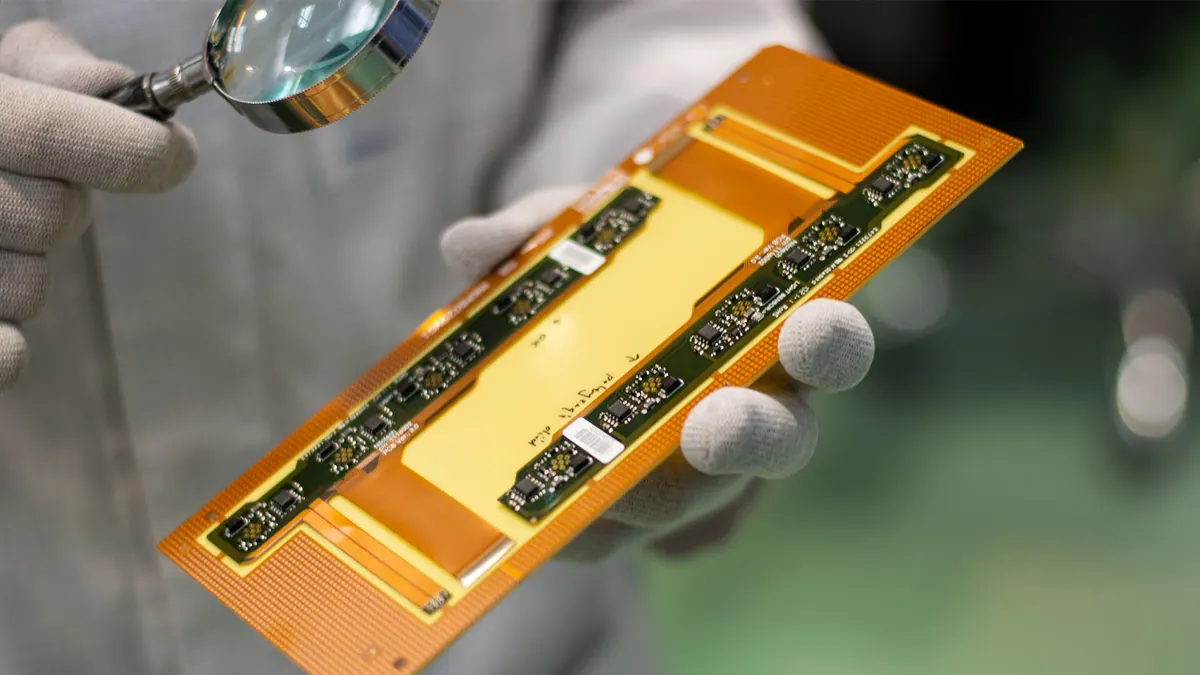
تولید فلکس پلیآمید PCB باید در مورد هدف خم، پوشش، سفتکنندهها، سیستم چسب، نوع مس، ضخامت انعطافپذیر، جابجایی پانل، بازرسی و پشتیبانی مونتاژ باشد. یک مدار فلکس یک PCB سفت و سخت با بستر نازکتر نیست. مورد استفاده مکانیکی بررسی تولید را کنترل می کند.
زمینه مهندسی
پلی آمید در مدارهای انعطاف پذیر رایج است زیرا از ساختارهای نازک و قابل خم شدن پشتیبانی می کند، اما نام ماده برای دقت نقل قول کافی نیست. خمیدگی های ایستا، خم شدن دینامیک، پشتیبانی از رابط، اجزای لحیم شده، لبه های سفت کننده، دهانه های پوششی و حامل های مونتاژ همگی می توانند فرضیات ساخت و PCBA را تغییر دهند.
هنگامی که خریدار به چک لیست آمادگی قیمت برای کار فلکس PCB یا مدار چاپی انعطاف پذیر نیاز دارد، از این صفحه استفاده کنید. هنگامی که جزایر صلب و بخش های انعطاف پذیر در یک ساختار یکپارچه لایه بندی شده اند، از صفحه انعطاف پذیر صلب استفاده کنید.
یادداشتهای مرور با پشتوانه منبع
- IPC-2223F مرز منبع برای زمینه طراحی تخته چاپی انعطافپذیر و انعطافپذیر است. بدون کپی کردن معیارهای پولی، از آن برای بررسی قاببندی منطقه خم، پشتهبندی، پوشش پوششی و سفتکننده استفاده کنید.
- IPC-6013E مرز منبع برای شرایط و زمینه عملکرد برد چاپی انعطاف پذیر است. از آن برای جدا کردن آمادگی طراحی از شواهد پذیرش استفاده کنید.
- NASA GSFC-STD-8001 فقط به عنوان چارچوب فرآیند QA محافظه کارانه برای بررسی PCB مبتنی بر قابلیت اطمینان استفاده می شود. این به معنای تایید ناسا یا قابلیت سخت افزار ماموریت نیست.
- محتوای موجود OminiPCB انعطاف پذیر PCB، rigid-flex، DFM، هزینه و زمینه آمادگی RFQ را فراهم می کند.
محدودیت های تولید
- هدف خمش استاتیک و دینامیک باید بیان شود زیرا مسیر مسی، خمیدگی ناحیه خمشی و بحث پذیرش را تغییر میدهد.
- دهانههای پوششی میتوانند بر دسترسی پد، لحیمکاری، عایقکاری و ثبت در اطراف ویژگیهای خوب تأثیر بگذارند.
- سفتکنندهها میتوانند اتصالات، اجزاء، پدهای تست، یا جابجایی مونتاژ را پشتیبانی کنند، اما مواد و محل لبه آنها باید مشخص شود.
- سیستم چسب، نوع مس، ضخامت تمام شده، و جابجایی های روی هم بر روی انعطاف پذیری، جابجایی و زمان هدایت تاثیر می گذارد.
- بخشهای انعطافپذیر نازک ممکن است برای SMT، AOI، برنامهنویسی، آزمایش یا ارسال به حاملهای پانل یا پشتیبانی فیکسچر نیاز داشته باشند.
ورودی های نقل قول
- Gerber یا ODB++، فایلهای مته، طرح کلی، جمعآوری، ترسیم خمشی، و هدف ضخامت تمام شده را دریل کنید.
- ضخامت پلیآمید، نوع مس، ترجیحات چسبنده یا بدون چسب در صورت نیاز، یادداشتهای پوششی و مواد سفتکننده.
- نواحی خمشی ایستا یا پویا، جهت خمیدگی، نواحی نگهدارنده، کانکتور و نکات پشتیبانی از اجزای لحیم شده.
- BOM، centroid، طراحی اسمبلی، فرضیات ثابت، برنامهنویسی یا تست عملکردی نیاز دارد که PCBA شامل شود.
- بازرسی، تست تداوم، بسته بندی، جابجایی، کمیت، زمان هدایت و نمونه اولیه در مقابل هدف تولید.
جدول تصمیم
| Flex PCB decision | چرا مهم است | شواهد RFQ |
|---|---|---|
| Static versus dynamic bend | Changes routing and reliability review. | Bend drawing, bend direction, installation condition, and keepout notes. |
| Coverlay design | Affects pad opening, insulation, and registration risk. | Coverlay layer, opening intent, soldering areas, and tolerance questions. |
| Stiffener placement | Controls connector support and SMT handling. | Stiffener material, thickness, outline, edge location, and support reason. |
| Copper and adhesive system | Changes flexibility, thickness, and fabrication process. | Stackup, copper type, adhesive note, and finished thickness target. |
| Assembly support | Thin flex can be damaged during SMT or test. | Carrier, fixture, panel handling, inspection, and packing assumptions. |
بررسی مثال
یک دم منعطف حسگر پوشیدنی با یک رابط ZIF، LED، یک حسگر لحیمشده، و یک خم دینامیک در نزدیکی لولای محفظه باید شامل جهت خم، ناحیه انعطافپذیر پویا، حفرههای هادی، دهانههای پوشش، مواد سفتکننده و ضخامت، ضخامت خم تمامشده، پشتیبانی کانکتور، __OMINI_TERM، گامهای همبستگی و عملکرد آزمایشی قبل از تست، باشد. نقل قول
ورودی های گمشده مشترک
- شواهد خمیدگی: شکل نصب شده، جهت خم، محل خم شدن، محفظه های اجزای نزدیک، و اینکه آیا فلکس یک بار خم شده است یا به طور مکرر در حال سرویس حرکت می کند را ارسال کنید.
- شواهد پشتیبانی: مواد سفت کننده، ضخامت، سمت چسب، پشتیبانی از ZIF یا رابط، پشتیبانی از پد تست، و نحوه ارتباط لبه های سفت کننده با ناحیه خمش را تعریف کنید.
- شواهد مونتاژ: بیان کنید که آیا قطعات روی فلکس نصب شدهاند، آیا حامل مجاز است، چگونه باید با پانلها کار کرد، و چه بازرسی یا بررسی تداومی مورد انتظار است.
- شواهد بستهبندی: مدارهای انعطافپذیر نازک ممکن است پس از آزمایش آسیب ببینند، بنابراین جابجایی، بستهبندی ESD، حفاظت در برابر خمیدگی و محدودیتهای حمل و نقل باید بخشی از RFQ باشد.
مبادلات
- یک کابل انعطاف پذیر ساده می تواند ارزان تر و سریعتر از انعطاف پذیر سخت باشد، زمانی که طراحی مکانیکی هنوز در حال حرکت است.
- فلکس پلیآمید میتواند وزن و تعداد اتصالات را کاهش دهد، اما بازبینی خم، پوشش، سفتکننده و هندلینگ را اجباری میکند.
- افزودن سختکنندهها به مونتاژ و قابلیت اطمینان اتصال کمک میکند، اما در صورت عدم بازبینی، میتواند تنش را به لبه سختکننده منتقل کند.
- محتوای Flex PCB باید برای منطق تصمیم گیری مکانیکی ذکر شود، نه برای اعداد شعاع خمشی جهانی پشتیبانی نشده.
CTA
درخواست یک نقل قول PCB هنگامی که بسته طراحی انعطافپذیر PCB قصد خم، پشته، پوشش، سفتکنندهها، پشتیبانی مونتاژ، و الزامات بازرسی را تعریف میکند.