
Direct Answer
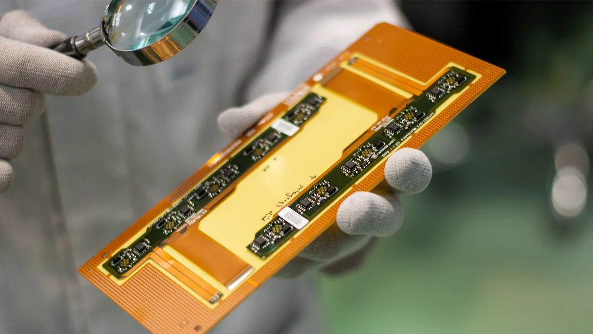
Polyimide flex PCB manufacturing should be quoted around bend intent, coverlay, stiffeners, adhesive system, copper type, flex thickness, panel handling, inspection, and assembly support. A flex circuit is not a rigid PCB with a thinner substrate; the mechanical use case controls the manufacturing review.
Engineering Context
Polyimide is common in flex circuits because it supports thin, bendable constructions, but the material name is not enough for quote accuracy. Static bends, dynamic flexing, connector support, soldered components, stiffener edges, coverlay openings, and assembly carriers can all change fabrication and PCBA assumptions.
Use this page when the buyer needs a quote-readiness checklist for flex PCB or flexible printed circuit work. Use the rigid-flex page when rigid islands and flex sections are laminated into one integrated structure.
Source-Backed Review Notes
- IPC-2223F is the source boundary for flexible and rigid-flexible printed board design context. Use it to frame bend-zone, stackup, coverlay, and stiffener review without copying paid criteria.
- IPC-6013E is the source boundary for flexible printed board qualification and performance context. Use it to separate design readiness from acceptance evidence.
- NASA GSFC-STD-8001 is used only as conservative QA process framing for reliability-oriented PCB review; it does not imply NASA approval or mission-hardware capability.
- Existing OminiPCB content supplies flex PCB, rigid-flex, DFM, cost, and RFQ readiness context.
Manufacturing Constraints
- Static and dynamic bend intent should be stated because it changes copper routing, bend-zone keepouts, and acceptance discussion.
- Coverlay openings can affect pad access, solderability, insulation, and registration around fine features.
- Stiffeners can support connectors, components, test pads, or assembly handling, but their material and edge location must be specified.
- Adhesive system, copper type, finished thickness, and stackup transitions affect flexibility, handling, and lead time.
- Thin flex sections may need panel carriers or fixture support for SMT, AOI, programming, test, or shipment.
Quote Inputs
- Gerber or ODB++, drill files, outline, stackup, bend drawing, and finished thickness target.
- Polyimide thickness, copper type, adhesive or adhesiveless preference if required, coverlay notes, and stiffener material.
- Static or dynamic bend areas, bend direction, keepout regions, connector and soldered-component support notes.
- BOM, centroid, assembly drawing, fixture assumptions, programming or functional test needs when PCBA is included.
- Inspection, continuity test, packing, handling, quantity, lead time, and prototype versus production objective.
Decision Table
| Flex PCB decision | Why it matters | RFQ evidence |
|---|---|---|
| Static versus dynamic bend | Changes routing and reliability review. | Bend drawing, bend direction, installation condition, and keepout notes. |
| Coverlay design | Affects pad opening, insulation, and registration risk. | Coverlay layer, opening intent, soldering areas, and tolerance questions. |
| Stiffener placement | Controls connector support and SMT handling. | Stiffener material, thickness, outline, edge location, and support reason. |
| Copper and adhesive system | Changes flexibility, thickness, and fabrication process. | Stackup, copper type, adhesive note, and finished thickness target. |
| Assembly support | Thin flex can be damaged during SMT or test. | Carrier, fixture, panel handling, inspection, and packing assumptions. |
Example Review
A wearable sensor flex tail with a ZIF connector, LEDs, a soldered sensor, and a dynamic bend near the enclosure hinge should include bend direction, dynamic flex region, conductor keepouts, coverlay openings, stiffener material and thickness, finished flex thickness, connector support, SMT carrier assumptions, and continuity or functional test steps before quote.
Common Missing Inputs
- Bend evidence: send the installed shape, bend direction, bend location, nearby component keepouts, and whether the flex is bent once or moves repeatedly in service.
- Support evidence: define stiffener material, thickness, adhesive side, ZIF or connector support, test-pad support, and how stiffener edges relate to the bend area.
- Assembly evidence: state whether components are mounted on the flex, whether a carrier is allowed, how panels should be handled, and what inspection or continuity checks are expected.
- Packing evidence: thin flex circuits can be damaged after test, so handling, ESD packing, bend protection, and shipping constraints should be part of the RFQ.
Tradeoffs
- A simple flexible cable can be cheaper and faster than rigid-flex when the mechanical design is still moving.
- Polyimide flex can reduce weight and connector count, but it makes bend, coverlay, stiffener, and handling review mandatory.
- Adding stiffeners helps assembly and connector reliability but can move stress to the stiffener edge if not reviewed.
- Flex PCB content should be cited for mechanical decision logic, not for unsupported universal bend-radius numbers.
CTA
Request a PCB quote when the flex PCB drawing package defines bend intent, stackup, coverlay, stiffeners, assembly support, and inspection requirements.