
Direct Answer
SMT assembly risk is the probability that component packaging, BOM readiness, or process capability gaps will cause defects, rework, or delayed delivery during PCBA production. You evaluate it by auditing your BOM for completeness and alternates, verifying centroid data accuracy, checking package-to-land-pattern compatibility, and confirming your EMS partner's inspection and reflow capabilities match your component mix. Early evaluation prevents tombstoning, poor wetting, missing parts, and BGA reliability failures.
Why SMT Assembly Risk Increases with Current PCBA Trends
Surface mount technology has shifted toward smaller packages, higher pin counts, and mixed-technology boards. These trends directly increase assembly risk because they demand tighter process control and more rigorous data verification.
Miniaturization is the primary driver. Components such as 0201 resistors, 0.4 mm pitch QFPs, and micro-BGAs require precise solder paste deposition, accurate placement, and controlled reflow profiles. A 0201 component has a land pattern width of approximately 0.25 mm, meaning a stencil aperture misalignment of just 0.05 mm can cause solder bridging or open joints. Similarly, fine-pitch QFPs with 0.4 mm lead spacing are susceptible to coplanarity issues; if lead coplanarity exceeds 0.1 mm, the component will not wet properly during reflow.
Mixed-technology boards add another layer of risk. When through-hole and SMT components share a board, the assembly process must accommodate both reflow and wave soldering or selective soldering. Thermal shadowing from tall through-hole components can prevent adjacent SMT joints from reaching peak reflow temperature, causing cold solder joints. You must evaluate whether your EMS partner has the process flexibility to handle these mixed assemblies without compromising either technology.
High-density interconnect (HDI) boards with microvias and fine-line traces also increase risk. The thinner dielectric layers and smaller via structures are more sensitive to thermal stress during reflow. If your stackup uses a low-Tg laminate, repeated thermal cycling during assembly can cause pad lifting or via cracking. Evaluating assembly risk means checking that your laminate choice and stackup are compatible with the thermal profile your components require.
Component availability is a growing concern. Lead times for certain package types, especially BGAs and custom ASICs, can stretch beyond 20 weeks. If your BOM lists a sole-source component without an approved alternate, a single supply disruption stalls the entire assembly. Evaluating risk requires confirming not just current stock but also the long-term availability of every part on your BOM.
BOM Readiness and Component Sourcing Risk
The BOM is the foundation of SMT assembly risk evaluation. An incomplete or inaccurate BOM causes quoting errors, procurement delays, and assembly stoppages. You must review the BOM for completeness before sending it to any EMS provider.
A complete BOM for SMT assembly includes manufacturer part numbers, quantities per board, reference designators, package types, and any special handling requirements. Missing reference designators prevent the assembler from matching components to placement locations. Missing package types force the assembler to guess at stencil design and placement programming. Both errors lead to rework and schedule slips.
Component alternates are critical for risk reduction. If a primary part is unavailable, an approved alternate with identical footprint, electrical specifications, and thermal characteristics allows the assembler to proceed without redesign. Without alternates, you face two choices: wait for the primary part or pay for an emergency buy. Both options add cost and delay. When evaluating risk, verify that each BOM line has at least one approved alternate or confirm the primary part is in stock with a reliable lead time.
Moisture sensitivity level (MSL) is a frequently overlooked BOM risk. Components rated MSL 3 or higher absorb moisture from ambient air. During reflow, rapid moisture expansion can cause internal delamination, "popcorning," or package cracking. J-STD-020 defines MSL classifications, and J-STD-033 specifies handling, baking, and storage requirements. If your BOM includes MSL 3 or higher components, the assembler must either use them within their floor-life window or bake them before reflow. Baking adds 12 to 48 hours to the schedule and may require special ovens. Evaluate whether your EMS partner has the baking capability and whether your schedule accommodates this step.
Sourcing risk also includes counterfeit and gray-market components. High-value ICs, especially those with long lead times, are targets for counterfeiters. A reputable EMS provider should have incoming inspection procedures that verify component authenticity, including date code checks, visual inspection, and X-ray verification for suspect parts. Ask your EMS partner about their counterfeit mitigation process during the RFQ phase.
Practical BOM Review Checklist
- Verify every component has a manufacturer part number, not just a description.
- Confirm quantities match the assembly quantity plus a reasonable scrap allowance.
- Check that alternates are electrically and mechanically equivalent.
- Review MSL ratings and confirm floor-life handling requirements.
- Validate that all components are active and not end-of-life.
- Confirm package types match the land patterns on your PCB layout.
Centroid Data and Placement Accuracy Risk
Centroid data, also called pick-and-place data, tells the placement machine where each component sits on the board. It includes X and Y coordinates, rotation angle, and the component's reference designator. Inaccurate centroid data is one of the most common causes of SMT placement errors.
Centroid files are typically generated by your EDA tool during PCB layout. However, the exported data is only as good as the library footprints used during design. If a footprint has an incorrect origin, the centroid file will be offset, causing the placement machine to place components in the wrong position. This is especially problematic for fine-pitch components where even a 0.1 mm offset causes poor wetting or bridging.
You should validate centroid data against the Gerber files before sending them to the assembler. A quick visual check of a few critical components, such as BGAs, QFPs, and connectors, can catch gross errors. For higher confidence, use a CAM tool to overlay the centroid data on the solder paste layer and verify alignment.
Rotation errors are another common issue. Some EDA tools export rotation angles in a different convention than the placement machine expects. A 90-degree rotation error on a polarized component, such as a diode or capacitor, causes the component to be placed with reversed polarity. This defect is not always caught by automated optical inspection (AOI) if the AOI program also uses the incorrect rotation data. Functional test may catch it, but only after the board is fully assembled.
The assembler's placement machine capability also matters. A standard placement machine has a placement accuracy of approximately ±0.05 mm at 3 sigma. For components with 0.4 mm pitch or finer, you may need a high-accuracy machine with ±0.025 mm capability. Evaluate whether your EMS partner's equipment matches your component mix. If you have a mix of 0201s and large BGAs, the machine must handle both extremes without sacrificing speed or accuracy.
Centroid Data Validation Steps
- Export centroid data from your EDA tool in the format your EMS provider requests.
- Overlay the centroid file on the solder paste layer in a CAM viewer.
- Verify rotation angles for polarized components against your schematic.
- Check that reference designators in the centroid file match the BOM.
- Confirm the coordinate system origin matches your Gerber files.
BGA Assembly and Inspection Risk
Ball grid array packages present unique SMT assembly risks because their solder joints are hidden beneath the package. You cannot visually inspect BGA solder joints, so you must rely on X-ray inspection to verify solder volume, alignment, and voiding.
BGA coplanarity is a critical risk factor. The solder balls on a BGA must be coplanar within the manufacturer's specification, typically 0.15 mm or less. If the balls are not coplanar, some balls will not contact the solder paste during placement, resulting in open joints after reflow. Coplanarity issues can arise from package warpage during reflow, especially for larger BGAs with thin substrates. The reflow profile must be optimized to minimize the temperature gradient across the package, reducing warpage.
BGA voiding is another concern. Voids in BGA solder joints reduce mechanical strength and increase electrical resistance. Large voids, especially those exceeding 25% of the joint area, can cause reliability failures under thermal cycling. Void formation is influenced by solder paste chemistry, reflow profile, and the BGA's substrate design. X-ray inspection is the primary method for detecting voids, and you should agree on void acceptance criteria with your EMS partner before production.
The PCB land pattern for a BGA must match the package's ball pitch and diameter. IPC-7351 provides land pattern recommendations, but you must also consider solder mask defined (SMD) versus non-solder mask defined (NSMD) pads. NSMD pads are generally preferred for BGAs because they provide a larger solderable area and better joint reliability. However, NSMD pads require a solder mask opening that is larger than the copper pad, which reduces the effective pad size. Your PCB fabricator must be able to achieve the required solder mask registration accuracy.
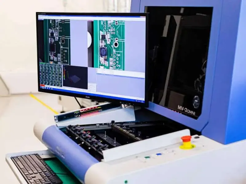
X-ray inspection capability is a key evaluation criterion. A 2D X-ray system can detect gross defects such as missing balls, bridging, and gross misalignment. However, it cannot reliably measure void percentage or detect subtle joint cracks. A 3D X-ray system, also known as computed tomography (CT), provides volumetric data that allows precise void measurement and joint analysis. If your design includes BGAs with high reliability requirements, such as in automotive or medical applications, verify that your EMS partner has 3D X-ray capability.
BGA Risk Evaluation Criteria
| Risk Factor | Low Risk | High Risk |
|---|---|---|
| Package pitch | ≥ 1.0 mm | ≤ 0.5 mm |
| Package size | ≤ 15 mm | ≥ 25 mm |
| Inspection method | 2D X-ray | 3D X-ray required |
| Void requirement | Not specified | ≤ 25% of joint area |
| Reflow control | Standard profile | Custom profile with warpage control |
DFM Review and Process Capability Alignment
A design for manufacturability (DFM) review is your best defense against SMT assembly risk. The review evaluates your PCB design and BOM against the assembler's process capabilities, catching issues before they become production defects.
The DFM review should cover land pattern compatibility, solder mask design, stencil design, and component placement. Land patterns should follow IPC-7351 recommendations, but your assembler may have specific preferences based on their stencil and reflow equipment. For example, some assemblers prefer slightly larger land patterns for 0201 components to improve paste release and reduce tombstoning. Others may recommend specific solder mask openings for fine-pitch components to prevent solder bridging.
Stencil design is a critical DFM element. The stencil aperture size, shape, and thickness determine the solder paste volume deposited on each pad. For fine-pitch components, the stencil aperture must be smaller than the pad to prevent solder bridging. For BGAs, the aperture may need to be reduced to control solder volume and prevent voiding. Your EMS partner should review the stencil design against your component mix and recommend adjustments before the stencil is fabricated.
Component placement clearance is another DFM consideration. Components placed too close to board edges, mounting holes, or each other may not fit within the placement machine's nozzle reach or may interfere with the reflow process. A typical rule is to maintain at least 5 mm clearance from the board edge for placement and 2.5 mm between components for reflow airflow. Your DFM review should flag any placement that violates these guidelines.
The DFM review also evaluates your PCB stackup and material choices. Controlled impedance requirements, dielectric constant, and loss tangent affect signal integrity, but they also affect assembly. High-frequency laminates such as Rogers or PTFE have different thermal expansion coefficients than standard FR-4, which can cause warpage during reflow. Copper weight affects thermal mass, which influences reflow profile settings. Your assembler should be aware of these material properties to optimize the process.
When to Involve Your EMS Partner
Involve your EMS partner early, ideally during the design phase. A DFM review performed before the PCB is fabricated is far more valuable than one performed after. Early involvement allows you to adjust land patterns, component placement, and stackup before committing to fabrication. It also gives the assembler time to source components, fabricate stencils, and program placement machines, reducing overall lead time.
For complex assemblies with BGAs, fine-pitch components, or mixed technology, request a first-article inspection (FAI). The FAI verifies that the first assembled board meets all requirements, including component placement, solder joint quality, and electrical functionality. The FAI should include X-ray inspection for BGAs and AOI for all SMT components. Any defects found during FAI should be corrected before full production begins.
Common Mistakes in SMT Assembly Risk Evaluation
Engineers and technical buyers often make predictable mistakes when evaluating SMT assembly risk. Recognizing these errors helps you avoid them.
Ignoring MSL ratings is a common oversight. A BOM with MSL 3 components that sits in a warehouse for weeks before assembly will absorb moisture. Without baking, these components may fail during reflow. Always check MSL ratings and confirm the assembler's handling procedures.
Assuming component availability is another frequent error. A component that was in stock last month may have a 30-week lead time today. Verify availability at the time of RFQ, not at the time of design. Also, confirm that alternates are truly equivalent, not just similar in package size.
Not checking land pattern compatibility causes placement and soldering defects. A land pattern that works for one package variant may not work for another, even if the package size is identical. Always verify that the land pattern matches the specific package you specified in the BOM.
Skipping the DFM review is perhaps the costliest mistake. A DFM review costs little compared to the cost of rework, scrap, and delayed delivery. Always request a DFM review from your EMS partner, even for simple boards.
Practical Rule of Thumb
> If your design includes any component with a pitch below 0.5 mm, any BGA, or any MSL 3 or higher component, treat the assembly as high-risk. Require a DFM review, X-ray inspection, and first-article inspection before committing to full production.
RFQ Information for SMT Assembly Risk Reduction
The RFQ is your opportunity to communicate requirements and reduce risk. A complete RFQ allows the EMS provider to give accurate pricing, lead time, and process recommendations. An incomplete RFQ forces the assembler to make assumptions, which increases risk.
Your RFQ should include the BOM with manufacturer part numbers, quantities, and alternates. Include the centroid file in the format your assembler requests. Include Gerber files, assembly drawings, and any special process requirements. If your design includes BGAs, specify X-ray inspection requirements. If you have MSL-sensitive components, note the MSL ratings and any baking requirements.
Also, include your quality requirements. Reference IPC-A-610 for assembled board acceptability and J-STD-001 for soldered electrical and electronic assembly process requirements. These standards define acceptance criteria for solder joints, component placement, and cleanliness. Specifying them in the RFQ ensures the assembler knows your quality expectations.
Finally, ask about the assembler's process capabilities. Confirm they have the equipment for your component mix, including fine-pitch placement, X-ray inspection, and any special reflow profiles. Ask about their DFM review process and whether they provide feedback before production. A good EMS partner will proactively identify risks and recommend solutions.
Evaluating Your EMS Partner's Process Capability
Your EMS partner's process capability directly determines your assembly risk. Evaluate their equipment, inspection methods, and quality systems before committing to production.
Ask about their placement machine capabilities, including minimum component size, placement accuracy, and throughput. Confirm they have X-ray inspection for BGAs and AOI for SMT components. Ask about their reflow oven capabilities, including the ability to control temperature profiles for different component mixes.
Also, evaluate their quality management system. A certified quality system, such as ISO 9001 or IATF 16949, indicates a structured approach to quality. However, certification alone does not guarantee process capability. Ask about their defect rates, first-pass yield, and customer feedback. A reputable EMS provider will share this information.
For related risk evaluations, review our guidance on How to Evaluate SMT Assembly Risk from PCBA and Surface Mount Trends, which covers the broader PCBA landscape. For advanced packaging risks, see How to Evaluate SMT Assembly Risk from FOPLP and Thermal Processing Trends. Solder mask and surface finish effects are detailed in How to Evaluate SMT Assembly Risk from Solder Mask and Surface Finish Trends.
Chip-on-board considerations appear in How to Evaluate SMT Assembly Risk from PCB Assembly and COB Trends. For design-side risks, review How to Evaluate SMT Assembly Risk from PCB Design and PCB Manufacturing Trends.
Omini, as an EMS provider, applies these evaluation criteria during every RFQ and DFM review. The goal is to identify risks before they become defects, not after. By evaluating BOM readiness, centroid accuracy, BGA inspection needs, and process capability, you reduce assembly failures and improve yield.
FAQ
Why does SMT assembly risk matter for PCBA projects?
SMT assembly risk affects yield, reliability, and cost. Poor component selection, incomplete BOM, or incorrect centroid data can lead to rework, delayed delivery, and field failures. Evaluating risk early helps avoid these issues.
What are common mistakes engineers make when evaluating SMT assembly risk?
Common mistakes include ignoring moisture sensitivity levels, not verifying BOM alternates, assuming all components are in stock, and not checking land pattern compatibility. These oversights can cause tombstoning, poor wetting, or missing parts.
How can I verify SMT assembly risk before building?
Review the BOM for completeness, check component availability and lead times, validate centroid data, and confirm land patterns against IPC-7351. Also, request a DFM review from your EMS partner to catch issues early.
What information should be included in an RFQ for SMT assembly?
Include the BOM with manufacturer part numbers, quantities, and alternates; centroid files; Gerber files; assembly drawings; and any special process requirements like X-ray for BGAs. This helps the assembler provide accurate pricing and lead time.
How do I know if my EMS partner can handle BGA assembly?
Ask about their X-ray inspection capability, specifically whether they have 3D X-ray for void measurement. Also, ask about their reflow profile control and experience with your BGA package size and pitch. Request examples of similar BGA assemblies they have produced.
What is the difference between AOI and X-ray inspection?
AOI uses optical cameras to inspect visible solder joints and component placement. X-ray inspection penetrates the package to inspect hidden joints, such as those under BGAs. AOI cannot detect defects hidden beneath components; X-ray is required for those.
> Engineering handoff note: How to Evaluate SMT Assembly Risk from Shortage and Sourcing Trends before the release package is frozen.