
Direct Answer
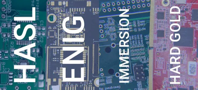
Evaluate SMT assembly risk by checking solder mask type and thickness against your component pitch, then matching surface finish to package coplanarity and environmental demands. Matte LPI solder mask with immersion silver is the safest default for standard FR-4 boards, but ENIG or ENEPIG becomes necessary for harsh environments, high-frequency designs, or extended storage. Verify mask registration, solder dam width, and finish thickness in fabrication data before ordering.
Why Solder Mask and Surface Finish Are Assembly Decisions, Not Cosmetic Choices
Solder mask and surface finish sit between the copper features you designed and the solder joints you need to produce. They affect paste release, wetting, coplanarity, impedance, and inspection reliability. A board can have perfect routing and still fail assembly if the mask traps solder balls or the finish does not wet properly with your reflow profile.
The engineering principle is straightforward: solder mask controls where solder can and cannot go, while surface finish controls how well solder wets to exposed copper. Both interact with your stencil design, reflow profile, and component package types. When you change one, you change the other's behavior. For example, a thick glossy mask over fine-pitch pads reduces the effective aperture area for paste release, while a rough HASL finish on a BGA pad creates coplanarity problems that AOI cannot always catch.
For a deeper look at how board layout and component placement interact with these material choices, see our guide on How to Evaluate SMT Assembly Risk from Board Design and Board Layout.
The Default Recommendation: Matte LPI Solder Mask with Immersion Silver
For most SMT assemblies on standard FR-4 with copper weights between 0.5 oz and 2 oz, use matte LPI (liquid photoimageable) solder mask with immersion silver surface finish. This combination balances cost, reliability, and assembly yield for the majority of designs.
Matte solder mask reduces solder ball risk because it provides a rougher surface that prevents solder from beading during reflow. It also improves solder paste release from the stencil apertures. Glossy masks, by contrast, can cause paste to stick to the aperture walls, leading to insufficient solder volume on pads.
Immersion silver provides a flat, coplanar surface suitable for fine-pitch QFPs, BGAs, and QFNs. It has good solderability with lead-free SAC305 profiles and does not introduce the magnetic losses associated with nickel-based finishes. For boards with controlled impedance requirements, immersion silver's thin, uniform deposition has minimal effect on trace impedance compared to thicker finishes.
Boundary Conditions for the Default
The default combination works when:
- Board thickness is between 0.8 mm and 2.4 mm
- Minimum pitch is 0.4 mm or larger
- Component count is moderate with standard reflow profiles
- Storage time before assembly is under six months
- The operating environment is not aggressively corrosive
When your design falls outside these conditions, you need to evaluate alternatives.
When to Switch from the Default: ENIG, ENEPIG, and HASL Tradeoffs
ENIG for Harsh Environments and Extended Storage
Switch to ENIG when the board will face humidity, temperature cycling, or long storage before assembly. ENIG's nickel barrier layer prevents copper diffusion through the finish, which preserves solderability over a longer shelf life. The gold layer protects the nickel from oxidation.
However, ENIG introduces two risks. First, the nickel layer is magnetic and contributes to conductor loss at high frequencies. Second, ENIG is susceptible to "black pad" — a brittle intermetallic fracture that occurs when the nickel layer corrodes during the immersion gold deposition process. Black pad is difficult to detect before assembly and can cause intermittent field failures.
For high-frequency designs above 1 GHz, consider ENEPIG instead. The palladium layer in ENEPIG prevents nickel corrosion and reduces the risk of black pad while maintaining good solder joint integrity.
HASL: Acceptable Only for Coarse-Pitch, Cost-Sensitive Boards
Lead-free HASL is still used for cost-sensitive boards with no fine-pitch or BGA components. The finish is applied by dipping the board in molten solder and removing excess with hot air. This creates an uneven surface with thickness variations that can exceed 25 microns across a single pad.
For packages with 0.5 mm pitch or smaller, HASL coplanarity issues cause tombstoning, solder bridging, and insufficient wetting. BGA packages are particularly problematic because the solder balls need a flat surface to collapse uniformly during reflow. If you must use HASL, restrict it to through-hole components and SMT parts with 0.65 mm pitch or larger.
OSP: A Cost-Effective Option with Short Shelf Life
Organic solderability preservative (OSP) is another option for boards assembled within weeks of fabrication. OSP provides a flat surface and good coplanarity, but it degrades quickly with multiple reflow cycles. If your board requires double-sided reflow or rework, OSP may not survive the second pass.
For a broader view of how PCB manufacturing trends affect assembly risk, review our analysis of How to Evaluate SMT Assembly Risk from PCB Design and PCB Manufacturing Trends.
Solder Mask Engineering: Thickness, Registration, and Solder Dam Width
Solder mask is not a binary on/off layer. Its thickness, registration accuracy, and minimum feature sizes directly affect assembly yield.
Mask Thickness and Paste Release
LPI solder mask typically deposits at 15 to 25 microns over copper, but thickness varies with copper weight and topography. Over thick copper traces (2 oz or more), the mask may be thinner at the edges of the trace, creating a "mask sliver" that can trap solder during reflow.
For fine-pitch components, the solder mask thickness between pads affects the effective stencil aperture. If the mask is too thick, it reduces the volume of paste that can be deposited. This is especially critical for 0.4 mm pitch QFNs where paste volume directly determines solder joint height.
Registration Tolerance and Mask Openings
Solder mask registration tolerance is typically ±75 microns for standard LPI processes, though some manufacturers achieve tighter. When the mask shifts, it can cover part of a pad (reducing solderable area) or expose copper outside the pad (creating solder bridges).
For BGA pads, mask registration errors are less critical because the solder balls self-align during reflow. But for fine-pitch QFPs and chip components, a mask shift of 50 microns can reduce the effective pad area by 20 percent, causing insufficient solder fillets.
Minimum Solder Dam Width
The solder dam is the mask material between adjacent pads. For standard LPI mask, the minimum reliable solder dam width is around 75 microns. Below this, the mask may peel or crack during thermal cycling.
When you have a 0.4 mm pitch QFP with 0.2 mm pad width, the space between pads is 0.2 mm (200 microns), which leaves a 50-micron solder dam on each side after registration tolerance. This is marginal. You have two options: reduce the pad width in the footprint (following IPC-7351 land pattern recommendations) or switch to a dry film solder mask that can achieve finer dams.
Controlled Impedance and Solder Mask
Solder mask affects controlled impedance because it changes the effective dielectric constant around the trace. A typical LPI mask has a dielectric constant of 3.3 to 3.8, compared to 4.2 to 4.5 for FR-4. When the mask covers a microstrip trace, it lowers the effective dielectric constant and increases impedance by 2 to 5 ohms.
For impedance-critical designs, specify the solder mask thickness and dielectric constant in your stackup documentation. Your manufacturer should account for this in their impedance calculation. If you do not specify, they will use their default values, which may not match your simulation.
Surface Finish Engineering: Coplanarity, Wetting, and Intermetallic Formation
Coplanarity and Fine-Pitch Packages
Coplanarity is the variation in height across a component's solderable surfaces. For BGA packages, the solder balls themselves provide some compliance, but the PCB surface finish must be flat enough for all balls to contact the pads during reflow.
Immersion silver deposits at 0.1 to 0.3 microns, creating a surface that follows the copper topography. ENIG deposits a thicker nickel layer (3 to 6 microns) that can amplify copper surface roughness. For high-density interconnect boards with fine lines and spaces, this amplification can create coplanarity issues.
Wetting and Reflow Profile Interaction
The surface finish must wet properly with your solder paste and reflow profile. Immersion silver wets well with SAC305 at peak temperatures of 235 to 245°C. ENIG also wets well, but the nickel layer requires slightly longer above liquidus to form a good intermetallic bond.
If your reflow profile is short and hot, ENIG may not form a complete intermetallic layer, resulting in weak solder joints. If your profile is long and cool, immersion silver may dissolve excessively into the solder, creating silver-tin intermetallics that weaken the joint.
X-Ray and AOI Inspection Considerations
Surface finish affects inspection reliability. ENIG's gold layer is highly reflective, which can cause AOI false calls on solder joint inspection. Immersion silver is less reflective but can tarnish, reducing AOI contrast over time.
For BGA and QFN packages, X-ray inspection is the primary method for detecting voids and bridging. The surface finish does not significantly affect X-ray images, but the solder mask color does — dark masks reduce contrast in X-ray images, making void detection more difficult.
For a practical review of how circuit board trends and material choices interact, see How to Evaluate SMT Assembly Risk from PCB Design and Circuit Board Trends.
Common Mistakes That Create Rework During DFM Review
Mistake 1: Specifying Glossy Solder Mask for SMT Boards
Glossy mask is cheaper and looks better in marketing photos, but it causes solder balls and poor paste release. The smooth surface allows solder to bead during reflow, creating conductive particles that can short adjacent pins. Always specify matte finish for SMT assemblies.
Mistake 2: Using HASL for BGA or Fine-Pitch Components
HASL's uneven surface makes BGA ball collapse unpredictable. You may get acceptable first-pass yield, but field failures from weak joints will appear months later. If cost is the driver, consider OSP with a short assembly turnaround instead.
Mistake 3: Ignoring Mask Registration in Fabrication Drawings
Your fabrication drawing should specify mask registration tolerance and minimum solder dam width. If you leave these unspecified, the manufacturer uses their default, which may not match your design's requirements. A 0.4 mm pitch QFN with 0.2 mm pads needs a tighter registration than a 1.27 mm pitch SOIC.
Mistake 4: Not Accounting for Solder Mask in Impedance Calculations
If your stackup simulation assumes bare copper but the board has solder mask over the traces, your measured impedance will be higher than simulated. This causes signal integrity issues that are difficult to debug after assembly. Always include solder mask in your impedance stackup.
Mistake 5: Choosing ENIG Without Checking Frequency Requirements
ENIG's nickel layer adds conductor loss at high frequencies. For designs above 1 GHz, ENEPIG or immersion silver is better. If you must use ENIG, account for the additional loss in your link budget.
Mistake 6: Overlooking Finish Compatibility with Rework
If your board requires rework, the surface finish must survive multiple heating cycles. Immersion silver can dissolve into solder during rework, leaving exposed copper that oxidizes. ENIG is more robust for rework but can form brittle intermetallics if reworked multiple times.
For guidance on how circuit symbols and footprint definitions affect assembly risk, review How to Evaluate SMT Assembly Risk from PCB Design and Circuit Symbols.
Decision Table: Solder Mask and Surface Finish Selection
| Design Condition | Recommended Solder Mask | Recommended Surface Finish | Key Risk to Manage |
|---|---|---|---|
| Standard FR-4, pitch ≥ 0.4 mm, < 6 months storage | Matte LPI | Immersion silver | Mask registration on fine-pitch pads |
| Harsh environment, long storage, multiple reflow cycles | Matte LPI | ENIG | Black pad, nickel corrosion |
| High-frequency design (> 1 GHz) | Matte LPI, controlled thickness | ENEPIG | Conductor loss from nickel |
| Cost-sensitive, pitch ≥ 0.65 mm, no BGA | Matte LPI | Lead-free HASL | Coplanarity, solder balls |
| Short turnaround (< 2 weeks), single reflow | Matte LPI | OSP | Shelf life, multiple reflow degradation |
| Controlled impedance critical | Matte LPI, specified Dk and thickness | Immersion silver | Impedance shift from mask |
Review Checklist for Solder Mask and Surface Finish
Before sending your design to assembly, verify the following items in your fabrication data:
- Solder mask type is specified as matte LPI (or dry film for fine-pitch designs)
- Mask thickness over copper is documented in the stackup
- Minimum solder dam width is specified and achievable for your pitch
- Mask registration tolerance is stated in the fabrication drawing
- Mask openings match pad sizes in the Gerber files
- No mask slivers exist between fine-pitch pads (check with CAM software)
- Surface finish type and thickness range are specified
- Finish is compatible with your reflow profile and component types
- Controlled impedance stackup includes solder mask Dk and thickness
- Surface finish is compatible with your inspection methods (AOI, X-ray)
- Storage time between fabrication and assembly is within finish shelf life
- Rework requirements are considered in finish selection
What to Ask Your Manufacturer
When you send your design for quotation, ask these questions:
1. What is your solder mask registration tolerance for LPI process? 2. Do you use matte finish as standard for SMT boards? 3. What is your minimum achievable solder dam width? 4. What surface finish thickness ranges do you guarantee? 5. Have you assembled this package type (BGA, QFN, 0.4 mm pitch) with this finish before? 6. Do you recommend any finish change based on my reflow profile or storage plans? 7. How does your solder mask affect controlled impedance on my stackup?
For designs that will receive conformal coating after assembly, check our guide on How to Evaluate SMT Assembly Risk from PCB Design and Conformal Coating to ensure your finish choice is compatible with the coating process.
Practical Manufacturing Notes
> Rule of thumb: If your design has any component with 0.4 mm pitch or smaller, or any BGA with more than 100 balls, do not use HASL. The coplanarity risk alone justifies the cost increase for immersion silver or ENIG.
> Caution: Solder mask color affects AOI performance. Dark green and black masks reduce contrast for solder joint inspection. If you need high inspection reliability, use lighter mask colors or specify AOI parameters that account for the mask color.
> Note on standards: IPC-A-610 defines acceptability criteria for assembled boards, while J-STD-001 covers process requirements for soldered electrical assemblies. Both standards reference solder joint quality but do not specify surface finish selection. IPC-4552, 4553, 4554, and 4556 are the specification families for ENIG, immersion silver, OSP, and ENEPIG respectively — your manufacturer should certify to the relevant specification for your chosen finish.
Final Evaluation Approach
The evaluation process is simple: define your operating conditions, component types, and storage requirements first. Then select solder mask and surface finish as a pair, not independently. Verify the selection against your fabrication data before ordering. Finally, confirm with your manufacturer that their process capabilities match your specifications.
Omini can review your fabrication data and assembly requirements together, ensuring your solder mask and surface finish choices align with your component packages and reflow profile. Send your design files early in the process to catch material compatibility issues before they become assembly problems.
The cost difference between a standard finish and a premium finish is small compared to the cost of rework, field failures, and delayed shipments. When in doubt, choose the more robust option — matte mask and immersion silver — and adjust only when your specific conditions require it.
> Engineering handoff note: How to Evaluate SMT Assembly Risk from Acquisition and CEO Trends before the release package is frozen.
> Engineering handoff note: How to Evaluate SMT Assembly Risk from Automotive and ADAS Trends before the release package is frozen.
> Engineering handoff note: How to Review Automotive PCBA Switch Design Risk Before Assembly before the release package is frozen.