
Direct Answer
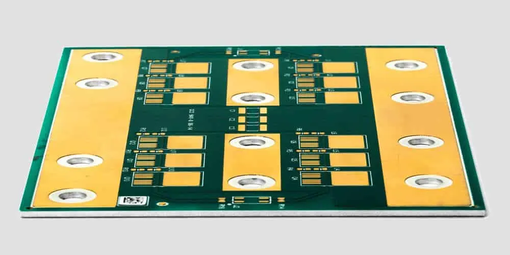
Metal core PCBs (MCPCBs) are designed to manage heat in high-power electronic applications by using a metallic base layer—usually aluminum or copper—instead of standard FR4. This metal core acts as a heat spreader, drawing thermal energy away from components and improving overall system reliability. They are commonly used in LED lighting, automotive power systems, and motor controllers where efficient heat dissipation is critical.
When designing an MCPCB, the goal is to optimize the thermal path from the component junction to the metal core while maintaining electrical insulation and mechanical stability. This involves careful selection of dielectric materials, via placement, and layer stackup to balance thermal performance with manufacturability and cost.
Thermal Via Design and Placement
Thermal vias are essential for transferring heat from the top circuit layer through the dielectric layer to the metal core. These vias should be placed directly under high-power components such as MOSFETs, LED arrays, or power resistors. A common practice is to use a via-in-pad or staggered via array beneath the component’s thermal pad to maximize heat flow.
The dielectric layer between the circuit and core must be thin enough to minimize thermal resistance but thick enough to provide adequate electrical isolation—typically ranging from 50 to 150 microns depending on voltage requirements. Using a thermally conductive but electrically insulating prepreg (such as ceramic-filled epoxy) helps achieve this balance.
For high-current designs, engineers often fill or cap thermal vias with conductive epoxy or copper to enhance thermal conductivity. However, this must be done during fabrication to avoid outgassing or voids that could compromise reliability. Omini’s DFM review includes validation of thermal via specifications to ensure they align with both thermal goals and manufacturing capabilities.
Layer Stackup and Material Selection
The standard MCPCB stackup consists of a copper circuit layer, a dielectric insulation layer, and a metal core (aluminum or copper). Aluminum is most common due to its low cost, light weight, and good thermal conductivity (~150 W/m·K). Copper cores offer higher thermal performance (~400 W/m·K) but are heavier and more expensive, making them suitable for extreme heat flux applications.
Circuit layer thickness typically ranges from 1 oz to 2 oz copper, depending on current carrying needs. Thicker copper improves lateral heat spreading but increases etching complexity. Designers should coordinate with their manufacturer early to confirm available materials and tolerances.
It’s also important to consider the coefficient of thermal expansion (CTE) mismatch between layers. While the metal core expands and contracts more than the dielectric and copper, proper material selection and symmetric design (where possible) help reduce warpage during thermal cycling.
Design Rules for Routing and Clearance
Routing on MCPCBs follows similar rules to standard PCBs, but with added attention to clearance near the edges. Since the metal core is conductive, any exposed copper near the board edge must be kept at a safe distance—usually at least 1.0 mm—to prevent shorting during depaneling or mounting.
Designers should also avoid placing high-voltage traces too close to the metal core, especially if it is grounded. Creepage and clearance distances must be verified based on the application’s voltage level and relevant safety standards (e.g., IEC 60950, UL 840). For guidance, refer to our detailed rules on PCB creepage and clearance design for high-voltage layouts.
Additionally, avoid sharp corners in copper pours near the dielectric/core interface to reduce stress concentration. Use teardrop connections and annular rings that meet via reliability standards—see our guide on PCB annular ring design rules for vias and plated through holes for best practices.
Via-in-Pad and HDI Considerations
In compact designs, such as those using BGAs or high-density arrays, via-in-pad may be necessary to save space and improve thermal coupling. However, on MCPCBs, via-in-pad requires careful planning because the dielectric layer is often thinner and less forgiving than in multilayer FR4 boards.
Via-in-pad should be plated and filled (via-in-pad plated over, or VIPPO) to prevent solder wicking and ensure a flat surface for component attachment. This process adds cost but is often justified in space-constrained, high-power designs. For more on implementing this technique, review our PCB via-in-pad design rules for BGA and HDI boards.
When using HDI techniques on MCPCBs, limit microvia depth to the dielectric layer only—avoid stacking microvias through the metal core, as drilling and plating through metal is not feasible with standard processes. All layer transitions should occur within the dielectric and copper layers above the core.
Surface Finish and Solder Mask
Surface finish selection affects both solderability and thermal performance. Common finishes include HASL, ENIG, and OSP. ENIG is preferred for MCPCBs in high-reliability applications due to its flat surface and oxidation resistance, especially when using fine-pitch components.
Solder mask must be compatible with the dielectric material and capable of withstanding the operating temperature. White solder mask is frequently used in LED MCPCBs to enhance light reflectivity, but it must be qualified for thermal stability to avoid discoloration or degradation over time.
Always include surface finish and solder mask specifications in your Gerber files and BOM notes. During prototyping, conduct a DFM check to confirm that the chosen finish is supported by your manufacturer’s line—Omini’s prototyping team routinely validates these parameters to avoid field failures.
DFM and Prototyping Best Practices
Before sending Gerber files to fabrication, run a full DFM check focused on MCPCB-specific risks: insufficient dielectric thickness, via-to-edge clearance, thermal via fill integrity, and metal core exposure. Many fabrication issues arise from assuming MCPCBs behave like FR4 boards—this leads to design rule violations during drilling, etching, or lamination.
Use panelization that accounts for the metal core’s rigidity. Aluminum cores are stiffer than FR4, which can affect depaneling method selection—routing or V-score may be preferred over breaking tabs. Confirm panel layout with your manufacturer to avoid mechanical stress during separation.
Prototyping an MCPCB should include thermal testing early in the process. Use thermal cameras or thermocouples to validate junction temperatures under load. If performance falls short, iterate on dielectric thickness, via density, or core material before committing to production.
For teams sourcing PCB assembly in China, refer to our guide on essential tips for finding a trusted PCB assembly manufacturer in China to ensure your MCPCB is assembled with proper thermal interface materials and reflow profiles suited to the substrate.
Closing Notes
Metal core PCB design requires a shift in mindset from pure electrical routing to electro-thermal co-design. Success depends on balancing thermal conductivity, electrical insulation, and mechanical stability—all while respecting the constraints of metal-based materials. By focusing on thermal via design, appropriate stackup, and close collaboration with an experienced manufacturer, engineers can avoid common pitfalls and deliver reliable, high-performance boards.
Whether you're prototyping a new LED array or scaling up a power inverter, treat the metal core not just as a structural layer but as an active thermal conduit. Validate assumptions early, design for manufacturability from the start, and leverage partnerships that understand both the electrical and thermal demands of your application.
Related Omini Engineering Notes
- Essential PCB Design Guidelines for Beginners: A Step-by-Step Approach
- PCB Annular Ring Design Rules for Vias and Plated Through Holes
- PCB Creepage and Clearance Design Rules for High-Voltage Layouts
- PCB Via-in-Pad Design Rules for BGA and HDI Boards
- Essential Tips for Finding a Trusted PCB Assembly Manufacturer in China