
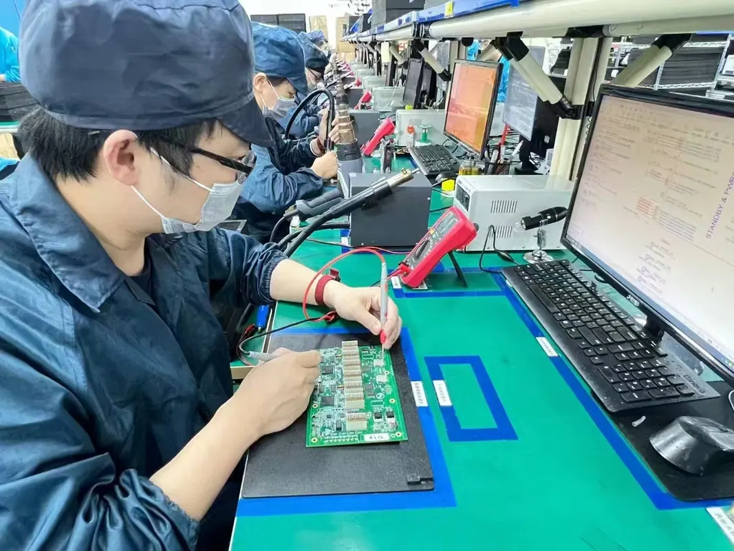
Direct Answer
Removing flux after soldering a PCB board requires matching the cleaning agent—such as high-purity isopropyl alcohol or aqueous saponifiers—to the specific flux chemistry and applying mechanical agitation or inline washing. For high-reliability electronics, post-solder flux residue must be completely removed to prevent electrochemical migration, dendritic growth, and current leakage.
Engineering teams choose between manual solvent brushing for prototype rework, batch ultrasonic cleaning for moderate assembly volumes, and inline aqueous spray-in-air systems using high-purity deionized (DI) water for high-density PCBA production. Selecting the optimal process depends on flux chemistry, component clearance, and cleanliness verification specifications.
> Manufacturing Rule of Thumb: Cleaning effectiveness is governed by the chemical matching rule: polar activators require polar solvents (water or alcohol), while non-polar resin bases require non-polar or saponified solvents. Mismatching the chemistry leaves white insoluble metal salts on the laminate.
Chemical Breakdown: Flux Types and Thermal Residues
Flux serves to remove oxides from copper pads and component leads during soldering, promoting wetting and intermetallic bond formation. However, flux residues left behind after reflow or wave soldering contain active chemical compounds that behave differently depending on the base formulation.
Rosin-Based Fluxes (R, RMA, RA)
Rosin flux formulations utilize natural pine resin or modified synthetic resins. Rosin (R) is non-corrosive and generally inert at room temperature. Rosin Mildly Activated (RMA) and Rosin Activated (RA) contain halide or organic acid activators that increase oxide removal efficiency. During the heating cycle of the Explained: What are the Steps in SMT Assembly Process?, heat polymerizes the resin base. The resulting glass-like residue encapsulates active halide ions. Solvent cleaners like Isopropyl Alcohol (IPA) or halogenated solvent blends are required to break down this polymerized resin matrix.
Water-Soluble / Organic Acid (OA) Fluxes
Water-Soluble fluxes rely on organic acids (such as citric, malic, or thiosulfate acids) combined with glycol or alcohol solvents. They exhibit aggressive oxide cleaning properties but leave highly corrosive ionic residues. Because these activators are strongly hydrophilic, they must be washed off completely using high-purity hot water (50°C to 70°C). If OA residues remain on a board, atmospheric moisture converts them into conducting electrolytes, causing rapid dendritic growth and metal migration across adjacent copper traces.
No-Clean Flux Chemistries
No-Clean fluxes are formulated with low solid content (typically 1.5% to 3.5% solids by weight) composed of weak organic acids (WOA) like succinic or adipic acid without rosin resins. When processed through a standard reflow profile, the heat decomposes the active acids, leaving minimal, non-conductive residue. Despite their name, No-Clean residues often must be removed if the assembly requires conformal coating, high-frequency signal integrity, or potting, as unreacted acids beneath component bodies can compromise coating adhesion or create micro-leakage channels in high-impedance circuits.
Manual Rework Cleaning vs. Automated Wash Systems
Selecting the right cleaning method requires evaluating production volume, component standoff constraints, and thermal limits. Production environments use standardized equipment configurations ranging from manual bench rework stations to high-throughput aqueous spray washers.
| Cleaning Method | Chemical Agent | Agitation Mechanism | Recommended Volume | Primary Application / Constraints |
|---|---|---|---|---|
| Manual Bench Solvent | Isopropyl Alcohol (99% pure), Solvent Blends | ESD-safe bristle brush, lint-free wipe | Prototypes, Field Rework | Labor-intensive; prone to re-depositing contaminated fluid across soldermask. |
| Batch Ultrasonic | Engineered Solvent / Aqueous Saponifier | Ultrasonic cavitation (40 kHz - 120 kHz) | Low to Medium Volume | Highly effective under low standoffs; risks mechanical damage to crystals or MEMS. |
| Vapor Degreasing | Fluorinated / Azeotropic Solvent Blends | Solvent vapor condensation + immersion | High-Reliability / Aerospace | Excellent solvency and fast drying; strict fluid containment required. |
| Inline Aqueous Spray | Deionized (DI) Water + Saponifier (5-15%) | High-pressure liquid spray jets (30-60 PSI) | High-Volume Production | Superior throughput; requires active water quality monitoring (>15 MΩ·cm). |
Manual Solvent Spot-Cleaning Protocol
For prototype rework or low-volume repairs, technicians rely on manual cleaning. To avoid spreading dissolved flux residue across the board, apply a 99% pure Isopropyl Alcohol solvent using a controlled dispenser. Scrub the target solder joint using an ESD-safe stiff brush, then immediately scrub with a fresh lint-free wiper before the solvent evaporates. Using low-purity alcohol (such as 70% rubbing alcohol) introduces water content that slows drying and deposits non-volatile impurities on the PCB surface.
Automated Inline Aqueous Washing
Automated aqueous washing systems utilize conveyor belt transportation through multiple isolated chambers: pre-wash, saponified wash, rinse, final DI water rinse, and forced air drying. Saponification converts non-water-soluble rosin residues into soluble soap complexes through alkaline chemical reactions. Saponifiers are blended with DI water at concentrations between 5% and 15% and sprayed through angled nozzles at elevated temperatures (55°C to 65°C). High-velocity air knives remove residual liquid droplets before the board enters the heat convection drying zone.
Component Clearance, HDI, and Substrate Dynamics
As component packages shrink, the mechanical dynamics of flux removal become significantly more complex. Modern board layouts feature tight component clearance, microvias, and flexible substrates that complicate cleaning fluid flow.
Low-Standoff Packages and Capillary Action
Bottom-Terminated Components (BTCs) such as Quad Flat No-Lead (QFN) packages, Land Grid Arrays (LGAs), and Ball Grid Arrays (BGAs) feature standoff clearances below 50 µm (2 mils). High surface tension prevents standard cleaning fluids from penetrating beneath these components. Flux entrapped in these tight spaces can boil during thermal cycle exposure or create low-resistance leakage paths across high-density pin groups.
To overcome surface tension, automated cleaning processes incorporate organic surfactants into wash fluids and raise fluid temperatures to reduce viscosity. Furthermore, angled high-impact spray jets (30° to 45° dynamic impingement angles) drive fluid through standoff voids beneath BGA arrays.
High-Density Interconnect (HDI) Microvias
When dealing with dense geometries, microvias in blind and buried configurations can trap liquid flux if poorly cleared. As detailed in our guide on Decoding High-Density Interconnect (HDI) PCB Technology: An Overview, tiny laser-drilled microvias beneath component footprints require low surface tension solvents to flush out entrapped chemistry during high-speed reflow cycles.
Substrate Flexibility and Surface Finish Considerations
When cleaning flexible or rigid-flex circuits, mechanical stress must be minimized. High-pressure spray jets can delaminate flex layers or damage exposed polyimide coverslips. Detailed instructions regarding flexible laminate handling can be reviewed in our overview on Flex PCB Manufacturing Process: An Overview for Beginners.
Similarly, surface finishes influence cleaning dynamics. Metallic finishes like ENIG (Electroless Nickel Immersion Gold) or OSP (Organic Solderability Preservatives) exhibit different chemical reactivities. Board designers selecting fabrication partners should consult Double Sided PCB Fabrication: How to Choose the Right Manufacturer to balance soldermask selection and chemical durability against target wash saponifiers.
For high thermal mass boards, residual heat retention affects how flux cures. Understanding these dynamics is essential when managing heat distribution on heavy copper designs, as explained in Common Failures in Heavy Copper PCB and How to Avoid Them in the Design Stage.
Cleanliness Verification and Industry Test Standards
Visual cleanliness inspection under 10x magnification is insufficient for high-reliability electronics. Microscopic ionic residues remain invisible to the human eye while driving latent field failures. Standards established by IPC provide strict qualification frameworks for post-assembly cleanliness.
Resistivity of Solvent Extract (ROSE) Testing
ROSE testing, governed by IPC-TM-650 Method 2.3.25, measures global ionic contamination. The assembled PCB is immersed in a dynamic mixture of 75% Isopropyl Alcohol and 25% deionized water. The system measures the change in electrical resistivity of the solvent solution as ionic species (like chloride, bromide, and sulfate ions) dissolve into solution.
- Standard industry threshold for military/industrial assemblies: < 1.56 µg/cm² of NaCl equivalent.
- Modern high-density production threshold: < 0.75 µg/cm² of NaCl equivalent.
While ROSE testing provides a fast, automated pass/fail metric for inline process monitoring, it cannot identify specific ionic species or pinpoint localized contamination under individual BGA components.
Ion Chromatography (IC)
Ion Chromatography isolates and quantifies exact concentrations of individual ionic species (such as $Cl^-$, $Br^-$, $F^-$, $SO_4^{2-}$, and weak organic acid anions). IC testing determines whether contamination stems from board fabrication residues, solder paste activators, or operator handling (such as skin salts).
Surface Insulation Resistance (SIR) Testing
SIR testing per IPC-TM-650 Method 2.6.3.7 evaluates the degradation of electrical resistance on interleaved comb patterns (test coupons). The coupon undergoes elevated environmental stress—typically 85°C temperature and 85% relative humidity under a constant DC bias voltage (e.g., 50V) for 168 hours. Drop-offs in insulation resistance ($< 10^8 \, \Omega$) signal electrochemical migration and dendrite growth paths.
Troubleshooting Common Flux Removal Defects
Improperly controlled wash parameters introduce secondary defect modes that compromise electronic reliability. Understanding the root causes of these defects allows manufacturing teams to correct wash chemistries quickly.
1. White Residue Formation
- Root Cause: Incomplete dissolution of metal carboxylate salts (lead/tin soaps formed by reaction of organic acid activators with solder) or incomplete breaking of the resin matrix.
- Correction: Increase saponifier concentration, raise fluid temperature to recommended threshold (60°C), or switch from generic IPA to engineered solvent blends formulated with co-solvents.
2. Entrapped Moisture Beneath Low-Standoff Packages
- Root Cause: Inadequate drying air volume or insufficient drying chamber temperature following water rinsing.
- Correction: Adjust air knife angles to force liquid out from under component margins, extend convection dry dwell time, and maintain drying enclosure temperatures between 90°C and 100°C.
3. Solder Mask and Marking Ink Degradation
- Root Cause: Chemical incompatibility between high-pH saponifiers ($pH > 11$) and soldermask polymers, or excessive ultrasonic bath dwell times.
- Correction: Keep saponifier pH bounded between 9.5 and 10.5, reduce wash cycle duration, and ensure base laminate materials comply with IPC-4101 specification requirements.
4. Component Wash Damage
- Root Cause: Immersion of unsealed components (e.g., open potentiometers, non-washable switches, unsealed relays, or MEMS microphones).
- Correction: Identify non-washable components during DFM review, route them for secondary hand soldering after main assembly washing, or apply temporary protective tape seals.
Practical Case Scenario: Cleaning Protocol for a Dense Mixed-Technology PCBA
Consider an industrial control PCBA featuring high-density digital circuitry, analog sensors, and power management components. Engineering teams must establish a validated cleaning process to ensure long-term field reliability.
Assembly Specifications
- Dimensions: 160 mm × 220 mm, 8-layer FR-4 laminate, 1.6 mm thickness.
- Components: 0.4 mm pitch QFNs, 0.8 mm pitch BGAs, 0402 passives, and bottom-terminated power FETs.
- Solder Chemistry: Water-Soluble Organic Acid (OA) lead-free solder paste reflowed with peak temperature of 245°C.
Executed Cleaning Procedure
1. Pre-Wash Inspection: Verify that all unsealed MEMS and non-washable components are omitted from initial SMT placement. 2. Inline Wash Stage: Process boards through an automated inline aqueous washer using a 10% saponifier concentrate at 60°C with dynamic fluid spray pressure set to 42 PSI. 3. Primary & Final DI Water Rinse: Rinse using high-purity deionized water ($18 \text{ M}\Omega\cdot\text{cm}$ resistivity at 50°C) to remove emulsified flux residues and saponifier traces. 4. Forced-Air Drying: Pass the board beneath dual high-velocity air knives set to 12° cross-angles, followed by a 6-minute forced hot-air convection chamber stage at 95°C. 5. Validation Testing: Run 2 boards per production lot through ROSE testing per IPC-TM-650 2.3.25. Acceptable baseline performance targets total ionic contamination below $0.45 \; \mu\text{g/cm}^2$ NaCl equivalent. 6. Post-Wash Secondary Assembly: Manually solder non-washable switches using No-Clean wire solder, followed by localized spot cleaning with IPA and lint-free wipes.
Practical Field Guidance for Post-Solder Cleaning
Establishing an effective post-solder flux cleaning regimen requires matching flux chemistries with compatible solvent or aqueous washing systems. Process parameters must balance cleaning efficiency against component compatibility and environmental constraints. At Omini, our assembly engineering teams evaluate board designs for component standoffs, wash compatibility, and ionic cleanliness targets during initial DFM reviews. By specifying clear cleanliness metrics early in product development, engineering teams ensure high assembly yield, robust solder joints, and reliable field operation across demanding applications.