
Direct Answer
Selecting a reliable PCB manufacturer requires evaluating technical capability, quality systems, DFM strength, and communication responsiveness before sending an RFQ. The right partner reduces schedule risk, prevents costly re-spins, and ensures your boards meet electrical and mechanical specifications. Focus on verifiable evidence of process control rather than marketing claims or certifications alone.
What You Are Really Trying to De-Risk
When you evaluate a PCB manufacturer, you are not just comparing prices or lead times. You are managing risk across three dimensions: technical risk, schedule risk, and cost risk. Technical risk means the board may not perform as designed due to material substitutions, impedance drift, or poor plating quality. Schedule risk means the manufacturer discovers manufacturability problems late, forcing re-spins or emergency engineering queries. Cost risk means hidden charges from incomplete files, BOM issues, or rework that inflate your original quote.
A reliable manufacturer reduces these risks through disciplined process control. That discipline shows up in how they handle your design files, how they respond to DFM questions, and what evidence they provide for testing and inspection. Before you send an RFQ, define your technical requirements precisely. Specify layer count, stackup, copper weight, surface finish, dielectric material, and impedance tolerances. If you cannot define these parameters, no manufacturer can quote accurately or build consistently.
The evaluation process should be structured, not intuitive. Use a supplier checklist that covers capability, quality certifications, DFM feedback, and communication responsiveness. Ask for specific evidence of process control, such as electrical test reports, impedance data, and material certifications. Certifications like ISO 9001 indicate a baseline quality management system, but they do not prove that a specific batch of boards will meet your requirements.
Technical Capability: Matching the Manufacturer to Your Board Type
Not all PCB manufacturers can handle every board type. A shop that excels at simple 2-layer prototypes may struggle with 12-layer HDI boards or rigid-flex constructions. Before evaluating suppliers, classify your board by its technical complexity. Consider layer count, minimum trace width and spacing, via types, aspect ratio, surface finish, and whether you need controlled impedance.
For standard rigid boards, IPC-2221 and IPC-2222 provide the general design framework for layout and dimensional requirements. These standards help you communicate your design rules clearly. For base material selection, IPC-4101 defines the specification system for laminate materials, covering properties like glass transition temperature, decomposition temperature, and dielectric constant. If your design requires specific laminate properties, reference the appropriate IPC-4101 slash sheet in your fabrication drawing.
For high-layer-count or HDI boards, ask the manufacturer about their experience with similar stackups. A reliable supplier will discuss via-in-pad processes, laser drilling capabilities, and sequential lamination steps. They should also explain how they handle impedance control, including the test coupon design and the measurement method they use. For boards requiring qualification to IPC-6012, confirm that the manufacturer can perform the required testing and provide the documentation.
For assembly services, the evaluation extends to component packaging, placement accuracy, and soldering processes. Ask about their experience with your package types, such as fine-pitch BGAs, QFNs, or through-hole connectors. Inquire about their reflow profile development and whether they perform X-ray inspection for BGA solder joints. A manufacturer that understands both fabrication and assembly can identify potential conflicts between your PCB design and your assembly process.
Quality Systems: Beyond Certifications to Evidence of Control
Quality certifications establish a baseline, but they do not guarantee your specific boards will be defect-free. ISO 9001 indicates that the manufacturer has a documented quality management system. IPC-6012 covers the qualification and performance requirements for rigid PCBs, including acceptable criteria for conductor spacing, plating thickness, and solderability. These certifications matter, but you should ask for evidence that the manufacturer actually follows their documented processes.
Request specific test reports and inspection data. For bare boards, ask for electrical test reports that show continuity and isolation test results. If your design requires controlled impedance, request impedance test data from the coupons on your panel. For material traceability, ask for material certifications that show the laminate batch and lot numbers. This documentation allows you to trace any future failure back to the specific materials and processes used.
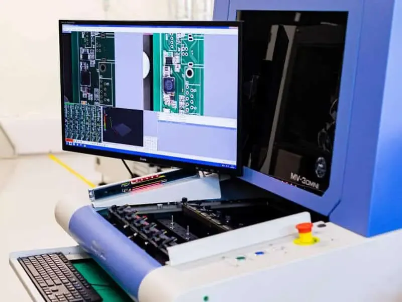
Inspection methods matter as much as test data. Ask how the manufacturer performs final inspection. Do they use automated optical inspection (AOI) for all boards? Do they perform microsection analysis for plated through-hole quality? How do they handle solder mask registration and surface finish verification? A manufacturer that can describe their inspection process in detail demonstrates a higher level of process control than one that only cites certifications.
For PCBA, ask about solder paste inspection (SPI), AOI after reflow, and X-ray inspection for hidden solder joints. Inquire about their component verification process, including how they handle counterfeit component risk and how they verify BOM compliance. A reliable EMS provider will have a documented incoming inspection process and will flag component issues before they reach the production line.
DFM Strength: The Manufacturer's First Test of Understanding
A manufacturer's DFM feedback is one of the most revealing signals of their capability. When you send your Gerbers, netlist, and fabrication drawing, a strong manufacturer will return a detailed DFM report that flags potential issues before production. This report demonstrates that they have actually reviewed your design and understand their own process limits.
Common DFM issues include insufficient annular ring, solder mask slivers, copper thieving problems, and impedance control challenges. A good DFM report will also flag issues with drill-to-copper spacing, minimum web between routed features, and surface finish compatibility with your assembly process. For example, if you specify ENIG for a board that will undergo multiple reflow cycles, the manufacturer should flag potential black pad concerns and suggest alternatives.
The quality of DFM feedback also reveals communication style. A manufacturer that asks specific, technical questions about your design is more reliable than one that accepts your files without comment. For example, if your stackup calls for 1 oz copper on all layers but your trace width and spacing suggest a different copper weight, a thorough manufacturer will ask for clarification. This kind of proactive communication prevents costly misunderstandings later.
DFM is not just about catching errors. It is also about optimizing manufacturability. A strong manufacturer will suggest panelization strategies that improve yield, recommend surface finishes that match your assembly process, and propose via structures that reduce cost without compromising performance. This level of engagement indicates that the manufacturer treats your project as a partnership, not just an order.
Cost and Schedule Drivers: What Actually Moves the Numbers
Cost and schedule are driven by design complexity, material selection, and process requirements, not by arbitrary manufacturer pricing. Understanding these drivers helps you evaluate quotes realistically and avoid surprises. The most significant cost drivers include layer count, board size, copper weight, surface finish, impedance control, and minimum feature sizes. Each of these factors affects material usage, processing time, and yield.
Material selection is a major cost driver. Standard FR-4 laminates are less expensive than high-Tg or low-loss materials. If your design does not require high-frequency performance or high-temperature operation, specifying standard materials can reduce cost. However, if your design requires controlled impedance, the manufacturer must use materials with consistent dielectric properties, which may limit your material choices.
Schedule risk comes from incomplete files, unclear specifications, and design changes after order placement. A manufacturer that performs thorough DFM before production reduces the risk of discovering manufacturability problems after fabrication begins. Component availability is another schedule risk for assembly. If your BOM includes long-lead-time components, the manufacturer should flag this early so you can plan accordingly.
Quote accuracy depends on the completeness of your files. Missing or ambiguous Gerbers, unclear layer stackup, undefined surface finish, or incomplete BOM can lead to inaccurate quotes and later change orders. Provide a detailed fabrication drawing with material, thickness, copper weight, impedance requirements, and tolerances. For assembly, provide component placement coordinates and any special process notes. Complete files enable accurate quoting and reduce the risk of miscommunication.
Supplier Qualification and RFQ Readiness Matrix
Use the following matrix to evaluate potential manufacturers before sending an RFQ. Score each criterion on a scale of 1 to 5, where 5 indicates strong evidence and 1 indicates no evidence or poor performance.
| Criterion | What to Evaluate | Evidence to Request |
|---|---|---|
| Technical capability | Experience with your board type (layer count, HDI, rigid-flex) | Case studies, process capability sheets, engineering discussion |
| Quality system | Certifications and process control documentation | ISO 9001, IPC-6012, IPC-4101 references, test reports |
| DFM strength | Quality of DFM feedback on sample files | Sample DFM report, engineering query response time |
| Inspection methods | AOI, microsection, electrical test, X-ray for assembly | Inspection process description, test report samples |
| Material traceability | Laminate and component traceability | Material certifications, lot traceability system |
| Communication | Responsiveness and technical depth of responses | Email response time, question quality, engineering support |
| Assembly capability | Experience with your package types and processes | Assembly capability sheet, reflow profile data, X-ray inspection |
| Cost transparency | Clarity of quote breakdown and change order policy | Itemized quote, terms and conditions |
For a deeper look at supplier evaluation, see our guide on Choosing the Right PCB Manufacturer in China: Key Factors to Consider. That article covers regional considerations and cultural communication factors that affect supplier relationships.
Practical Steps Before Sending Your RFQ
Before you send your RFQ, complete these steps to reduce risk and improve quote accuracy. First, verify that your Gerber files are complete and correct. Use a Gerber viewer to check that all layers are present and that the file format is consistent. Include a netlist so the manufacturer can verify connectivity during electrical test. Second, create a detailed fabrication drawing that specifies material, thickness, copper weight, surface finish, solder mask color, silkscreen requirements, and dimensional tolerances.
Third, define your impedance requirements explicitly. Specify the target impedance, tolerance, and the layers that require controlled impedance. Include stackup details and note whether you require impedance test coupons. Fourth, for assembly, provide a complete BOM with manufacturer part numbers, reference designators, and any alternates. Include component placement coordinates and any special process notes, such as selective soldering or conformal coating requirements.
Fifth, review your design for common manufacturability issues before sending it. Check annular ring sizes, drill-to-copper spacing, and solder mask slivers. If you are unsure about a specific design rule, ask the manufacturer before you send the RFQ. A quick engineering query can prevent a costly re-spin later.
> Practical note: A common mistake is sending files without a fabrication drawing and expecting the manufacturer to infer your requirements. This almost always leads to quote inaccuracies and change orders. The fabrication drawing is your primary communication tool for defining what you need.
Communication and Engineering Support: The Hidden Differentiator
Communication quality is a reliable predictor of manufacturing success. A manufacturer that responds quickly with specific, technical answers is more likely to catch problems early and keep your project on schedule. Evaluate how they handle engineering queries during the RFQ process. Do they ask clarifying questions about your stackup or impedance requirements? Do they provide DFM feedback without being asked? Do they explain their process limitations clearly?
A manufacturer that treats engineering queries as an opportunity to improve your design is more valuable than one that simply processes your files. For example, if your design uses a surface finish that is incompatible with your assembly process, a good manufacturer will flag this and suggest alternatives. This kind of proactive support reduces the risk of field failures and assembly defects.
For assembly projects, communication extends to component sourcing and BOM management. Ask how the manufacturer handles component shortages, obsolescence, and alternates. A reliable EMS provider will have a structured process for component verification and will communicate any substitution requests before making changes. This transparency protects your design integrity and avoids surprises during production.
For more guidance on evaluating suppliers, see How to Choose a Reliable PCB Manufacturer for Your Project and Essential Factors to Consider When Choosing a PCB Fabrication Partner. Both articles provide additional checklists and evaluation frameworks.
Understanding the RFQ and DFM Cycle
The RFQ process is not a one-way transaction. It is a dialogue that reveals how the manufacturer works. When you send your files, expect a response that includes a quote, a DFM report, and engineering questions. The quality of this response tells you a lot about the manufacturer's process discipline. A quote that arrives without any engineering questions may indicate that the manufacturer did not thoroughly review your files.
The DFM cycle is where most schedule risk is eliminated. A thorough DFM review will identify potential issues before production, allowing you to correct them in the design phase. This is far less expensive than discovering problems after fabrication. Plan for at least one DFM iteration in your schedule, especially for complex boards. This planning reduces the risk of re-spins and keeps your project on track.
For custom boards, the RFQ and DFM process is even more critical. As explained in Custom PCB Is a Product-Specific Board: RFQ, Cost, and DFM, custom boards require careful specification of materials, tolerances, and test requirements. The RFQ process is your opportunity to align with the manufacturer on all these parameters before production begins.
Testing and Approval: What to Verify Before You Approve Production
Before you approve production, verify that the manufacturer has addressed all DFM findings and that you agree on the final stackup, materials, and test requirements. Confirm the electrical test method, whether it is flying probe or fixture-based, and whether it covers all nets. For controlled impedance boards, confirm that test coupons will be included on the panel and that impedance data will be provided.
For assembly, confirm the inspection methods that will be used. Ask about SPI, AOI, and X-ray inspection coverage. Inquire about how the manufacturer will handle any solder defects found during inspection. A reliable EMS provider will have a documented rework process and will communicate any deviations from the approved process.
Finally, establish a clear approval process for any deviations or substitutions. If the manufacturer proposes a material substitution or a component alternate, require written approval before proceeding. This protects your design intent and ensures that any changes are documented and traceable.
FAQ
What factors affect the accuracy of a PCB manufacturing quote?
Quote accuracy depends on the completeness and correctness of your files. Missing or ambiguous Gerbers, unclear layer stackup, undefined surface finish, or incomplete BOM can lead to inaccurate quotes and later change orders. Provide a detailed fabrication drawing with material, thickness, copper weight, impedance requirements, and tolerances.
What files are needed to get a reliable PCB quote?
You need Gerber files (RS-274X or X2), a netlist, a fabrication drawing, and a BOM for assembly. For controlled impedance, include stackup details and impedance test coupons. For assembly, provide component placement coordinates and any special process notes. Complete files enable accurate quoting and reduce the risk of miscommunication.
How do I compare different PCB manufacturers?
Compare them on technical capability, quality systems, DFM feedback, and communication. Ask about their experience with your board type, their inspection methods, and how they handle engineering queries. Review their DFM reports and responsiveness. Do not compare only on price; consider total cost including rework and delays.
What risks can cause delays in PCB manufacturing?
Common risks include incomplete or incorrect files, unclear stackup, component availability issues, and lack of DFM feedback. If the manufacturer does not perform thorough DFM, you may discover manufacturability problems only after fabrication. Changes in BOM or design after order placement can also cause significant delays.
Why is DFM feedback important when choosing a PCB manufacturer?
DFM feedback reveals how well the manufacturer understands your design and its capabilities. A good DFM report will flag potential issues like insufficient annular ring, solder mask slivers, or impedance control challenges. This helps you correct errors before production, saving time and money.
What should I look for in a PCB manufacturer's quality certifications?
Look for certifications like ISO 9001 for quality management and IPC-6012 for rigid PCB qualification. These indicate a baseline of process control. However, certifications alone are not enough. Ask for specific evidence of testing, such as electrical test reports, impedance test data, and material certifications.
For projects that include full system assembly, also review our guidance on Key Factors to Consider When Choosing a Box Build Assembly Manufacturer. Box build projects add enclosure, cabling, and system-level testing considerations that require additional supplier evaluation criteria.
Omini can serve as your manufacturing partner for both PCB fabrication and assembly, providing engineering support throughout the RFQ and DFM process. Our team evaluates your files for manufacturability, communicates clearly about process capabilities, and provides the documentation you need to verify quality.