
Direct Answer
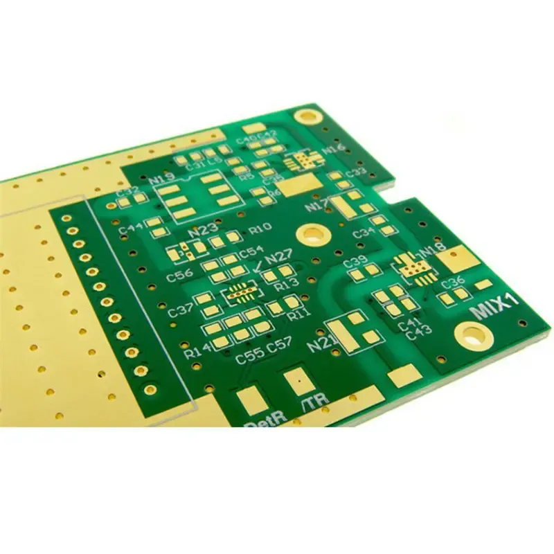
Microwave PCBs are high-frequency circuit boards designed to transmit and receive signals above 1 GHz with minimal loss and distortion, using specialized low-loss laminates, controlled impedance stackups, and tighter manufacturing tolerances than standard FR-4 boards. They are essential for radar, 5G, satellite, and aerospace systems where signal integrity at microwave frequencies determines whether the entire system works or fails.
---
Why Standard FR-4 Fails at Microwave Frequencies
Standard FR-4 is a glass-reinforced epoxy laminate that works well for digital circuits below a few hundred megahertz, but it becomes a serious bottleneck above 1 GHz. The dielectric constant (Dk) of FR-4 typically ranges from 4.2 to 4.8, but it varies significantly with frequency and temperature. At microwave frequencies, this variation causes impedance drift, signal skew, and unpredictable phase behavior. More importantly, FR-4 has a loss tangent (Df) around 0.020, meaning the material absorbs a meaningful portion of the signal energy as heat. At 10 GHz, that loss becomes unacceptable for most systems.
The engineering solution is to switch to low-loss laminates such as Rogers RT/duroid, PTFE-based materials, or hydrocarbon ceramic laminates. These materials offer dielectric constants in the 2.2 to 3.5 range and loss tangents below 0.002 at high frequencies. The choice of laminate directly determines insertion loss, phase stability, and the board's ability to maintain consistent impedance across the operating band. For any system operating above 1 GHz—radar, 5G backhaul, satellite links, or automotive sensing—the laminate and stackup are the first engineering decisions that define performance.
Why Standard FR-4 Fails at Microwave Frequencies
FR-4 is a glass-reinforced epoxy laminate with a dielectric constant (Dk) around 4.2 to 4.8 and a loss tangent (Df) that rises sharply above 1 GHz. At 10 GHz, FR-4 can exhibit a loss tangent of 0.020 or higher, which translates into excessive dielectric loss and signal attenuation. A 10 cm microstrip trace on FR-4 at 10 GHz can lose several decibels of signal power, which is unacceptable for radar, 5G, or satellite links where every dB matters.
The second problem with FR-4 is Dk instability. The dielectric constant of standard FR-4 varies with frequency and temperature, causing impedance drift. A trace designed for 50 ohms at 1 GHz may measure 55 ohms at 10 GHz. This impedance mismatch creates reflections that degrade the signal-to-noise ratio and increase bit error rates in digital systems.
Microwave PCBs replace FR-4 with laminates engineered for predictable high-frequency behavior. Materials like Rogers RO4003C, Rogers RT/duroid, PTFE-based laminates, and ceramic-filled hydrocarbon compounds offer stable dielectric constants and low loss tangents across the operating band. These materials, combined with controlled impedance design rules, allow engineers to build reliable circuits for radar, 5G, satellite, and test equipment applications.
---
Why Standard FR-4 Fails Above 1 GHz
FR-4 is a glass-reinforced epoxy laminate with a dielectric constant (Dk) that varies significantly with frequency and temperature. At 1 GHz and above, FR-4's loss tangent (Df) climbs to roughly 0.020–0.025, which translates to high insertion loss per unit length. A 6-inch microstrip trace on FR-4 at 2.4 GHz can lose several dB of signal energy, which is unacceptable for receivers and transmitters that need clean amplitude and phase response.
The problem is not just attenuation. FR-4's Dk also drifts with temperature and moisture absorption, causing impedance values to shift outside the tolerance required by high-speed digital or RF front-end designs. When a trace is supposed to be 50 ohms and the dielectric constant changes, the characteristic impedance changes too, which creates reflections and standing waves. For a radar or 5G link, that behavior degrades the signal-to-noise ratio and can push the system out of specification.
Microwave PCB materials solve this with predictable, low-loss laminates. PTFE-based substrates, hydrocarbon ceramic laminates like Rogers RO4003C, and woven-glass-reinforced thermoset materials offer stable dielectric constants and low dissipation factors at microwave frequencies. The choice of laminate, copper foil profile, and stackup construction determines how much signal energy is preserved from the transmitter to the antenna or receiver.
---
Why Standard FR-4 Fails Above 1 GHz
FR-4 is a glass-reinforced epoxy laminate with a dielectric constant (Dk) that drifts with frequency and a loss tangent (Df) that becomes unacceptable above roughly 1 GHz. At 2.4 GHz, a typical FR-4 board can show insertion loss above 0.2 dB per inch, and that number climbs quickly as frequency increases. For a 5G mmWave link at 28 GHz, FR-4 losses become so severe that the signal may be unusable after just a few centimeters of trace.
The problem is not only attenuation. FR-4's dielectric constant varies with frequency and temperature, which shifts the characteristic impedance of a trace away from the target value. That impedance mismatch creates reflections, standing waves, and degraded eye diagrams in digital systems. For radar, satellite links, and 5G backhaul, these effects directly reduce link budget and bit error rate performance.
Microwave PCB materials are selected for two primary electrical properties: dielectric constant (Dk) and loss tangent (Df). Dk determines the propagation velocity and characteristic impedance of the trace, while Df measures how much energy the substrate absorbs at frequency. Standard FR-4 has a Df around 0.020 at 1 GHz, while PTFE-based laminates can achieve Df below 0.002. That difference translates into dramatically lower insertion loss at microwave frequencies.
The manufacturing process also changes. Microwave boards require controlled impedance verification, tighter etch tolerances, and often specialized surface finishes. The design review must account for copper roughness, via stubs, and reference plane continuity. These factors make microwave PCBs more expensive and slower to produce than standard boards, but they are non-negotiable for reliable high-frequency operation.
What Makes a PCB "Microwave-Grade"
A microwave PCB is defined by its operating frequency, material properties, and the manufacturing controls applied during fabrication. The term "microwave" generally refers to frequencies from 1 GHz up to 30 GHz and beyond, where the wavelength becomes short enough that standard PCB materials and design rules no longer work reliably.
Why FR-4 Fails Above 1 GHz
Standard FR-4 has a dielectric constant (Dk) around 4.2 to 4.5 and a loss tangent (Df) of roughly 0.020 at 1 GHz. At higher frequencies, FR-4's loss tangent causes significant signal attenuation, and its Dk varies with frequency and temperature. This leads to impedance drift, excessive insertion loss, and timing errors in high-speed digital or RF systems. For a 10 GHz signal, FR-4 can attenuate the signal so severely that the receiver cannot distinguish it from noise.
Microwave laminates address this with lower loss tangents, typically 0.002 to 0.009 depending on material grade, and more stable dielectric constants across frequency and temperature. Common choices include Rogers RO4000 series, PTFE-based laminates, and hydrocarbon ceramic composites. These materials maintain consistent electrical properties at microwave frequencies, which is why they are specified for radar, 5G, satellite, and automotive applications.
What Defines a Microwave PCB
A microwave PCB is any circuit board engineered to operate at frequencies above 1 GHz, where the electrical behavior of the substrate, copper, and transitions becomes the dominant factor in system performance. At these frequencies, the wavelength shrinks to centimeters or millimeters, so even small variations in dielectric constant, trace width, or substrate thickness can cause impedance mismatches, reflections, and excessive insertion loss.
The engineering difference between a standard PCB and a microwave PCB is not just the material. It is the entire design and manufacturing chain: laminate selection, stackup construction, copper surface treatment, via transitions, and test methodology. Standard FR-4 has a dielectric constant (Dk) around 4.2 to 4.5 with a loss tangent (Df) near 0.020 at 1 GHz. At 10 GHz, FR-4 becomes highly lossy, and its Dk drifts with frequency and temperature. Microwave laminates such as Rogers RO4003C, RO4350B, or PTFE-based materials hold a more stable Dk and a much lower Df, typically below 0.003 at 10 GHz.
What Defines a Microwave PCB
A microwave PCB is any circuit board engineered to operate in the microwave frequency range, generally accepted as 1 GHz and above. The distinction is not just about frequency; it is about how the board material, stackup, and fabrication processes interact with the electrical signal.
Standard FR-4 has a dielectric constant (Dk) around 4.2 to 4.5 and a loss tangent (Df) of roughly 0.020 at 1 GHz. At higher frequencies, FR-4's loss tangent causes significant signal attenuation, and its Dk varies with frequency, leading to impedance drift and timing errors. Microwave PCB laminates such as Rogers RT/duroid, Rogers RO4000 series, PTFE-based materials, and hydrocarbon ceramic laminates offer Dk values from 2.2 to 10.2 with loss tangents below 0.002 at 10 GHz. These materials preserve signal amplitude and phase, which is why they are mandatory for radar, 5G, satellite, and high-speed test equipment.
The engineering shift from FR-4 to microwave laminates affects every downstream decision: stackup design, copper foil selection, via construction, surface finish, and assembly process. This article explains what changes, why it matters, and how to avoid the most common design and sourcing mistakes.
Why Standard FR-4 Fails Above 1 GHz
FR-4 is a glass-reinforced epoxy laminate with a dielectric constant (Dk) around 4.2 to 4.5 and a loss tangent (Df) near 0.020 at 1 GHz. At microwave frequencies, these values become problematic. The loss tangent determines how much signal energy converts to heat as it travels through the dielectric. At 10 GHz, standard FR-4 can exhibit insertion loss above 0.5 dB per inch, which is unacceptable for most RF systems.
The dielectric constant of FR-4 also varies significantly with frequency and temperature. This variation causes impedance drift, which leads to signal reflections and degraded return loss. For a 50-ohm controlled impedance trace, a Dk shift from 4.2 to 4.5 can change the characteristic impedance by several ohms, which is enough to cause measurable mismatch in a 5G or radar front end.
Microwave PCBs replace FR-4 with laminates engineered for stable Dk and low loss tangent (Df) at high frequencies. Common choices include Rogers RO4003C, Rogers RT/duroid, PTFE-based laminates, and ceramic-filled hydrocarbon materials. These substrates maintain consistent electrical properties across the operating band and reduce dielectric absorption, which is the dominant loss mechanism above 1 GHz.
What Defines a Microwave PCB
A microwave PCB is defined by its operating frequency range, material system, and the manufacturing controls required to preserve signal integrity at those frequencies. In practice, this means the board is built around a laminate with a stable dielectric constant (Dk) and a low loss tangent (Df), a stackup engineered for controlled impedance, and surface finishes that do not degrade high-frequency performance.
Standard FR-4 has a loss tangent around 0.020 at 1 GHz, which rises sharply with frequency. At 10 GHz, FR-4 can attenuate signals so severely that the board becomes unusable for most RF applications. Microwave laminates such as Rogers RT/duroid, Rogers RO4000 series, PTFE-based materials, and ceramic-filled hydrocarbon laminates offer loss tangents in the range of 0.001 to 0.004. That difference translates directly into lower insertion loss, better signal-to-noise ratio, and more consistent phase behavior across the operating band.
The manufacturing implications are equally important. Microwave PCBs require tighter dielectric thickness control, controlled impedance verification, and surface finishes that do not degrade high-frequency performance. Standard FR-4 processes cannot deliver the repeatable electrical properties that a 10 GHz radar or 28 GHz 5G link demands.
What Makes a PCB "Microwave-Grade"
A PCB becomes a microwave PCB when the operating frequency forces you to change material, stackup, and fabrication choices. The threshold is generally accepted as 1 GHz, though many designs at 500 MHz already benefit from microwave-grade materials. Above 1 GHz, the wavelength shrinks to the point where standard FR-4's dielectric losses and dimensional instability cause unacceptable signal degradation.
The Role of Laminate Materials
The single most important decision in a microwave PCB is the laminate selection. FR-4 has a dielectric constant (Dk) that varies significantly with frequency, and its loss tangent (Df) is too high for reliable high-frequency operation. At 10 GHz, standard FR-4 can exhibit insertion loss above 0.2 dB/cm, which quickly becomes unmanageable over even short trace runs.
Microwave laminates fall into several categories:
- PTFE-based laminates (e.g., Rogers RT/duroid, Teflon): Very low Dk (2.2–3.0) and low loss tangent (0.001–0.002), ideal for frequencies above 10 GHz.
- Hydrocarbon ceramic laminates (e.g., Rogers RO4000 series): Lower cost than PTFE, stable Dk around 3.0–3.5, good for 5G and radar applications.
- Hybrid laminates: Mixing FR-4 with high-frequency materials to reduce cost while preserving critical signal layers.
The material choice directly affects insertion loss, phase stability, and impedance control. A standard FR-4 board has a loss tangent around 0.020 at 1 GHz, while PTFE-based laminates can be as low as 0.0015. That difference becomes significant when signal integrity matters at 10 GHz or higher.
---
What Makes a PCB "Microwave" and Why FR-4 Fails
A PCB earns the microwave designation based on operating frequency, not board thickness or layer count. When signals exceed roughly 1 GHz, the electrical properties of the substrate dominate performance. Standard FR-4 has a dielectric constant (Dk) around 4.2 to 4.5 and a loss tangent (Df) of 0.020 or higher. At microwave frequencies, that loss tangent translates directly into signal attenuation: the higher the Df, the more energy is converted to heat as the signal travels through the dielectric.
The practical consequence is that FR-4 becomes unusable above a few gigahertz for most applications. A 6-inch trace on FR-4 at 5 GHz can lose several dB of signal power, which is unacceptable for radar, 5G, or satellite links. Microwave PCBs replace FR-4 with laminates such as Rogers RO4003C, Rogers RT/duroid, PTFE-based materials, or ceramic-filled hydrocarbon laminates. These materials offer a stable dielectric constant (Dk) and a low loss tangent (Df), typically below 0.005 at operating frequency, which keeps insertion loss predictable and signal integrity intact.
---
What Makes a PCB "Microwave-Grade"
A PCB becomes a microwave PCB when the operating frequency exceeds roughly 1 GHz. At these frequencies, the electrical properties of the substrate dominate performance. Standard FR-4 has a loss tangent around 0.020 at 1 GHz, which causes significant signal attenuation. Microwave laminates such as Rogers RO4003C, Rogers RT/duroid 5880, or PTFE-based materials offer loss tangents in the range of 0.001 to 0.003, making them suitable for high-frequency signal propagation.
The material choice is the first major decision. The dielectric constant (Dk) determines the propagation velocity and characteristic impedance of the traces. The loss tangent (Df) determines how much energy is dissipated as heat. Both values shift with frequency, temperature, and moisture absorption, so you must verify the laminate datasheet at your operating frequency rather than assuming the 1 MHz or 10 GHz values are identical. For example, a PTFE-based laminate with a Dk of 3.0 at 10 GHz may exhibit a different effective Dk after etching and lamination, which directly affects your impedance calculation.
What Makes Microwave PCBs Different from Standard PCBs
Standard FR-4 has a loss tangent around 0.020 at 1 GHz, which rises sharply with frequency. At 10 GHz, FR-4 can attenuate signals so severely that the received power falls below the system noise floor. Microwave PCBs replace FR-4 with low-loss laminates such as Rogers RT/duroid, Rogers RO4000 series, PTFE-based materials, or ceramic-filled hydrocarbon laminates. These materials offer loss tangents in the range of 0.001 to 0.004, which is 5 to 20 times lower than FR-4 at microwave frequencies.
The material choice also affects the dielectric constant (Dk). FR-4 typically has a Dk of 4.2 to 4.8 with poor tolerance, while microwave laminates offer Dk values from 2.2 to 10.2 with tighter tolerances of ±0.02 or better. This matters because impedance is directly tied to Dk. A variation in Dk shifts the characteristic impedance of a 50-ohm trace, causing reflections and reducing the usable bandwidth of the system.
---
Why Standard FR-4 Fails Above 1 GHz
Standard FR-4 is a glass-reinforced epoxy laminate that works well for digital boards below a few hundred megahertz. Above roughly 1 GHz, FR-4 exhibits a loss tangent (Df) of 0.020 or higher, which converts signal energy into heat. The dielectric constant (Dk) of FR-4 also varies significantly with frequency, which makes impedance unpredictable across the operating band.
The practical result is simple: a 50-ohm trace designed on FR-4 at 1 GHz will not maintain its impedance at 5 GHz. Insertion loss climbs, return loss degrades, and radiated emissions increase. For radar, 5G, satellite, and high-speed test equipment, that behavior is unacceptable.
Microwave PCBs replace FR-4 with low-loss laminates such as Rogers RT/duroid, PTFE-based materials, or ceramic-filled hydrocarbon composites. These materials have a stable dielectric constant (Dk) and a low loss tangent (Df) across the operating frequency range. The copper foil, surface finish, and stackup construction are also selected to minimize conductor and dielectric losses.
---
What Makes a PCB "Microwave-Grade"
A microwave PCB is defined by its operating frequency range, not by its physical size or layer count. In practice, boards that handle signals above 1 GHz—often up to 40 GHz or beyond in millimeter-wave systems—require materials and fabrication steps that standard digital PCBs do not use.
The Role of Laminate Materials
Standard FR-4 has a dielectric constant (Dk) around 4.2 to 4.5 and a loss tangent (Df) near 0.020 at 1 GHz. At microwave frequencies, FR-4's loss tangent causes excessive signal attenuation, and its Dk varies significantly with frequency and temperature. This leads to impedance drift, timing errors, and degraded signal-to-noise ratios.
Microwave PCBs use laminates with a lower and more stable Dk, typically between 2.2 and 3.5, and a loss tangent below 0.002 at the operating frequency. Common material families include:
- PTFE-based laminates (e.g., Rogers RT/duroid series)
- Hydrocarbon ceramic laminates (e.g., Rogers RO4000 series)
- Cross-linked polystyrene and other thermoset microwave materials
These laminates maintain consistent electrical properties across frequency and temperature, which is essential for phase-sensitive applications like radar and 5G beamforming.
What Makes a PCB "Microwave-Grade"
A microwave PCB is defined by its operating frequency, not its size or layer count. Once a signal crosses roughly 1 GHz, standard FR-4 becomes a poor substrate because its dielectric constant (Dk) drifts with frequency and its loss tangent (Df) causes excessive attenuation. The board material, copper surface, and stackup must all be engineered to preserve signal integrity at these frequencies.
The three defining characteristics of a microwave PCB are:
- Low-loss laminate: Materials like Rogers RT/duroid, PTFE, or hydrocarbon ceramic laminates have a stable Dk and a low dissipation factor (Df) at microwave frequencies.
- Controlled impedance: Trace width, dielectric thickness, and copper weight are calculated and held to tight tolerances to maintain a consistent characteristic impedance.
- Surface and transition control: Copper roughness, via stubs, and solder mask over high-frequency traces all affect insertion loss and return loss.
Standard FR-4 is not suitable for microwave designs because its Dk varies significantly with frequency and its loss tangent is too high. At 10 GHz, a typical FR-4 board can show more than 1 dB/inch of loss, while a PTFE-based laminate can hold that below 0.1 dB/inch depending on the specific material grade.
What Makes a PCB "Microwave-Grade"
A microwave PCB is defined by its operating frequency, not by its physical size or layer count. When a board carries signals above 1 GHz, the wavelength becomes short enough that trace dimensions, dielectric thickness, and material properties directly affect signal behavior. Standard FR-4 has a loss tangent around 0.020 at 1 GHz, which rises with frequency and causes unacceptable attenuation for most microwave systems.
The material choice is the first major decision. Low-loss laminates such as Rogers RO4003C, RO4350B, PTFE-based substrates, and ceramic-filled hydrocarbon materials offer dielectric constants (Dk) between 2.2 and 3.5 and loss tangents (Df) below 0.003 at 10 GHz. FR-4, by contrast, typically has a Df of 0.020 or higher, which means significantly more signal energy is converted into heat. For a 10 GHz trace, that difference can translate into several decibels of additional insertion loss per inch, which is unacceptable for radar, 5G, or satellite links.
The choice of laminate also affects the stackup. Microwave boards often use thinner dielectrics to maintain controlled impedance with narrower trace widths. A common stackup might use Rogers RO4003C with a dielectric constant of 3.38 and a dissipation factor of 0.0027 at 10 GHz, paired with 0.5 oz or 1 oz copper. The material's Dk stability across temperature and frequency matters more here than in standard digital boards, because any variation shifts the impedance and phase response of the circuit.
---
Why Standard FR-4 Fails at Microwave Frequencies
Standard FR-4 is a glass-reinforced epoxy laminate with a dielectric constant (Dk) around 4.2 to 4.8 and a loss tangent (Df) that rises sharply above 1 GHz. At microwave frequencies, FR-4 exhibits high dielectric loss, meaning the substrate itself absorbs signal energy and converts it into heat. The result is excessive insertion loss, signal attenuation, and unpredictable impedance behavior that can make a design non-functional.
The problem is not just the base material. FR-4's dielectric constant varies significantly with frequency and temperature. A trace designed for 50 ohms at 1 GHz may measure 45 ohms at 10 GHz because the Dk drifts. For narrowband or wideband systems, that shift destroys return loss and increases bit error rate. Microwave laminates like Rogers RT/duroid, Rogers 4000 series, PTFE-based substrates, and ceramic-filled hydrocarbon materials offer stable Dk values across frequency and temperature, plus a low dissipation factor (Df) that reduces dielectric loss.
Copper surface roughness also matters more at microwave frequencies. Standard electrodeposited copper has a rough profile that increases conductor loss as frequency rises. High-frequency laminates often pair with rolled copper or low-profile treated copper to reduce skin effect losses. The material choice, copper type, and surface finish all interact, so the stackup must be reviewed as a system rather than as individual material selections.
---
Why Standard FR-4 Fails Above 1 GHz
Standard FR-4 is a glass-reinforced epoxy laminate with a dielectric constant (Dk) that varies significantly with frequency and temperature. At 1 GHz and above, FR-4 exhibits a loss tangent (Df) in the range of 0.015 to 0.025, which translates to excessive dielectric absorption and conductor losses. Signal integrity degrades quickly, and impedance control becomes unreliable because FR-4's Dk can shift by 5–10% across a board depending on resin content and glass weave style.
Microwave laminates such as Rogers RO4003C, RO4350B, PTFE-based materials, and hydrocarbon ceramic laminates offer a much lower loss tangent, typically below 0.003 at 10 GHz. They also provide more stable dielectric constants across frequency and temperature. This stability matters because the impedance of a transmission line depends directly on the square root of the dielectric constant. If Dk drifts, your characteristic impedance drifts with it, causing reflections and insertion loss that degrade the signal.
The manufacturing consequences are immediate. Standard FR-4 processing assumes a certain etch tolerance, drill registration, and surface finish that are acceptable at lower frequencies. At microwave frequencies, those same tolerances can produce impedance mismatches, excessive radiation, and unpredictable phase behavior. A microwave PCB requires controlled impedance verification, tighter dielectric thickness control, and careful attention to copper surface roughness and via transitions.
---
What Defines a Microwave PCB in Manufacturing Terms
A microwave PCB is defined by its operating frequency, not by its physical size or layer count. In manufacturing terms, the board must maintain a consistent characteristic impedance across every trace, transition, and connector launch. The dielectric material must have a stable dielectric constant (Dk) and a low loss tangent (Df) at the operating frequency, because standard FR-4 becomes lossy and unpredictable above roughly 1 GHz.
The most common microwave laminates are PTFE-based materials such as Rogers RT/duroid, Rogers RO4000 series, and Taconic laminates. These materials offer Dk values in the 2.2 to 3.5 range with loss tangents below 0.002 at 10 GHz, whereas standard FR-4 typically has a loss tangent around 0.020 at the same frequency. That difference translates directly into signal attenuation: a 10 GHz trace on FR-4 can lose several decibels per inch, while a PTFE-based laminate may lose less than 0.1 dB per inch under the same conditions.
The manufacturing consequences are immediate. Standard FR-4 etching tolerances, drill registration, and surface finishes that work fine at 100 MHz become unacceptable at 5 GHz or 10 GHz. Microwave PCB fabrication requires controlled impedance verification, tighter dielectric thickness control, and careful attention to copper surface roughness. The material cost alone is often 5 to 10 times higher than FR-4, and lead times are longer because specialty laminates are not stocked by every fabricator.
---
What Makes a PCB "Microwave-Grade"
A PCB becomes a microwave PCB when its operating frequency exceeds roughly 1 GHz, where the electrical properties of the laminate and the physical geometry of the traces dominate performance. At these frequencies, the wavelength shrinks to centimeters or millimeters, so even small variations in dielectric thickness, trace width, or copper surface finish can cause measurable signal degradation.
The two material properties that matter most are the dielectric constant (Dk) and the loss tangent (Df). Dk determines the propagation velocity and the characteristic impedance of the transmission line. Df, also called the dissipation factor, quantifies how much energy the substrate absorbs as heat. Standard FR-4 has a Dk around 4.2 to 4.5 and a Df near 0.020 at 1 GHz, which becomes unacceptable above a few gigahertz. Microwave laminates such as Rogers RT/duroid, Rogers RO4000 series, PTFE-based materials, and ceramic-filled hydrocarbon laminates offer Df values below 0.002 at 10 GHz, reducing signal attenuation dramatically.
The choice of laminate is not just about the dielectric constant. You must also consider the stability of Dk across temperature and frequency, the coefficient of thermal expansion (CTE), and how the material behaves during multilayer lamination. PTFE-based laminates, for example, are soft and require plasma etching before plating copper. Rogers RO4003C and similar hydrocarbon ceramics are more rigid and easier to process while still delivering low loss. Standard FR-4 has a loss tangent around 0.020 at 1 GHz, while microwave-grade materials like Rogers RO4350B sit near 0.0037. That difference directly determines how much signal energy is converted into heat along the trace.
What Defines a Microwave PCB
A microwave PCB is any circuit board engineered for signals above roughly 1 GHz, where wavelength becomes short enough that trace geometry, dielectric properties, and transitions dominate electrical performance. In manufacturing terms, the board must be treated as a precision transmission-line structure rather than a simple interconnect. The three defining characteristics are the laminate system, the controlled impedance stackup, and the fabrication tolerances applied to copper features and dielectric spacing.
Standard FR-4 has a dielectric constant (Dk) around 4.2 to 4.5 and a loss tangent (Df) that rises sharply above 1 GHz. At 10 GHz, FR-4 can exhibit loss tangent values near 0.020 or higher, which translates into excessive attenuation and signal heating. Microwave PCB materials such as Rogers RT/duroid, PTFE-based laminates, or ceramic-filled hydrocarbon laminates offer Df values in the range of 0.001 to 0.004 at high frequencies. This difference is the primary reason why material selection is the first decision in a microwave PCB design.
The operating frequency is the starting point for every material decision. Below 1 GHz, FR-4 can often work if the trace lengths are short and the impedance tolerance is not too tight. Above 1 GHz, dielectric loss and conductor loss begin to dominate. At 10 GHz and beyond, even the copper surface finish and the glass weave style of the laminate affect performance. The material choice must therefore be made before the stackup is defined, not after the schematic is complete.
What Makes a PCB "Microwave-Grade"
A microwave PCB is defined by its electrical performance at high frequency, not by its physical size or layer count. The board must maintain signal integrity across a specified frequency band, typically above 1 GHz, where standard FR-4 becomes lossy and unpredictable.
The key difference is the laminate. FR-4 has a dielectric constant (Dk) around 4.2 to 4.8 with a loss tangent (Df) near 0.020 at 1 GHz. At higher frequencies, FR-4's loss tangent rises sharply, causing excessive signal attenuation. Microwave-grade laminates like Rogers RT/duroid, Rogers RO4000 series, PTFE-based materials, and ceramic-filled hydrocarbon laminates offer Df values between 0.001 and 0.004. That is an order of magnitude lower than FR-4, which directly reduces insertion loss per centimeter of trace.
The choice of laminate also affects the dielectric constant stability. Standard FR-4 has a Dk that varies with frequency and temperature, which shifts impedance and phase response. Microwave laminates are engineered for stable Dk across frequency and temperature, which matters for phase-sensitive applications like radar beamforming and satellite links. When you specify a microwave PCB, you are not just choosing a different color board; you are selecting a material system with controlled electrical properties that determine whether your design meets its link budget.
What Defines a Microwave PCB
A microwave PCB is any circuit board engineered to operate at frequencies above 1 GHz, where the electrical behavior of the substrate, copper, and transitions becomes the dominant factor in circuit performance. Unlike standard digital boards where signal integrity issues appear at higher harmonics, microwave boards face these challenges at the fundamental operating frequency.
The material system is the first and most important difference. Standard FR-4 has a dielectric constant (Dk) around 4.2 to 4.5 and a loss tangent (Df) of roughly 0.020 at 1 GHz. At 10 GHz, FR-4's loss tangent climbs and its Dk drifts with frequency, causing both excessive attenuation and unpredictable impedance. Microwave laminates such as Rogers RT/duroid, Rogers RO4000 series, and PTFE-based materials offer Df values between 0.001 and 0.004, which means far less signal energy is converted into heat. The choice of laminate is the single largest factor in high-frequency performance, and it directly affects cost, stackup design, and fabrication method.
The operating frequency determines the material class you need. Below roughly 1 GHz, standard FR-4 can still work for many designs. Above that, you should evaluate a low-loss laminate. At 10 GHz and beyond, even small differences in dielectric constant (Dk) and loss tangent (Df) dominate the link budget. A material with Dk of 3.0 and Df of 0.0015 will behave very differently from FR-4 with Dk around 4.3 and Df near 0.020. The difference is not subtle; it is the difference between a working link and one that fails to close.
What Defines a Microwave PCB
A microwave PCB is any circuit board engineered to operate at frequencies at or above 1 GHz, where standard board materials and conventional layout rules no longer deliver predictable performance. At these frequencies, the wavelength shrinks to centimeters or millimeters, and the physical geometry of traces, dielectrics, and transitions becomes electrically significant. What works at 100 MHz will often fail at 5 GHz because parasitic capacitance, inductance, and dielectric losses scale with frequency.
The engineering definition is practical: a microwave PCB is a board whose material properties, stackup, and manufacturing tolerances are chosen specifically to preserve signal integrity at microwave frequencies. This means the laminate's dielectric constant (Dk) and loss tangent (Df) must be stable across the operating band, the copper roughness must be controlled, and the impedance of every transmission line must be predictable within tight tolerances.
What Makes Microwave PCBs Different from Standard PCBs
Standard FR-4 has a loss tangent around 0.020 at 1 GHz, which rises quickly with frequency. At 10 GHz, FR-4 can attenuate signals so severely that the received signal becomes unusable. Microwave laminates such as Rogers RT/duroid, Rogers RO4000 series, PTFE-based materials, and ceramic-filled hydrocarbon laminates offer loss tangents in the range of 0.001 to 0.004. That difference of one order of magnitude is why material selection is the first decision that separates a working microwave board from a failed prototype.
The second major difference is stackup control. Standard FR-4 boards often have dielectric thickness tolerances of ±10% or worse. A 10% variation in dielectric thickness directly shifts the characteristic impedance of a microstrip trace. At 10 GHz, that shift can push a 50-ohm trace to 55 ohms or more, causing reflections that degrade the signal. Microwave laminates are manufactured with tighter Dk and thickness tolerances, and the stackup is designed around the target impedance from the start.
The third difference is manufacturing discipline. Microwave PCBs require careful control of copper surface roughness, via transitions, and surface finish. Standard board shops that are not set up for high-frequency work may not have the etching tolerance, plasma desmear, or impedance verification equipment needed. This is why microwave PCB fabrication is usually handled by manufacturers with dedicated RF experience and test capability.
---
What Makes a PCB a Microwave PCB
A PCB becomes a microwave PCB when the operating frequency enters the microwave range, generally above 1 GHz. At these frequencies, the electrical wavelength shrinks to centimeters or millimeters, so trace dimensions, dielectric thickness, and material properties become electrically significant. A trace that behaves as a simple conductor at 100 MHz starts acting as a transmission line at 2 GHz, and its characteristic impedance must be controlled to prevent reflections.
The engineering shift is not just about speed. At microwave frequencies, the laminate's dielectric constant (Dk) and loss tangent (Df) dominate performance. Standard FR-4 has a Dk that varies with frequency and a Df around 0.020, which causes excessive attenuation and phase distortion. Microwave laminates such as Rogers RT/duroid, Rogers RO4000 series, PTFE-based materials, and hydrocarbon ceramics offer Df values below 0.002 at 10 GHz. That is an order of magnitude lower loss, which is why material selection is the first decision in any microwave PCB design.
The manufacturing consequences follow directly from the material. PTFE and ceramic-filled laminates are softer, more sensitive to moisture, and require different drilling and plating processes than FR-4. Copper foil roughness, which is often ignored in standard board design, becomes a dominant loss factor above 10 GHz. A smooth copper surface, such as rolled copper or low-profile foil, reduces conductor loss but may affect adhesion. The design team must balance electrical performance against manufacturability, and that balance starts with the stackup.
What Defines a Microwave PCB
A microwave PCB is a circuit board engineered to maintain signal integrity at frequencies where standard board materials and processes introduce unacceptable losses. The practical threshold is typically 1 GHz and above, though many designs operate at 10 GHz, 28 GHz, or even 77 GHz for automotive radar. At these frequencies, the wavelength shrinks to centimeters or millimeters, so trace dimensions, dielectric thickness, and material properties become electrically significant.
The core difference from a standard PCB is the laminate system. FR-4 has a dielectric constant (Dk) around 4.2 to 4.5 and a loss tangent (Df) that rises sharply above 1 GHz, causing excessive attenuation and phase error. Microwave PCBs use low-loss laminates such as Rogers RT/duroid, Rogers RO4000 series, PTFE-based materials, or ceramic-filled hydrocarbon laminates. These materials offer a more stable Dk and a much lower Df, which directly reduces signal loss at high frequencies.
The selection of laminate is driven by the operating frequency, the required impedance tolerance, and the thermal environment. For example, a 5G mm
> Engineering handoff note: Gold Finger PCBs: A Comprehensive Overview of Their Applications, Circuit Board Manufacturing Process: A practical reference for Beginners, and Electronics Manufacturing Process: A practical reference before the release package is frozen.
> Also compare Copper Core PCBs: Revolutionizing the Electronics Industry and Explained: What are the Steps in SMT Assembly Process? before locking the quote scope.