
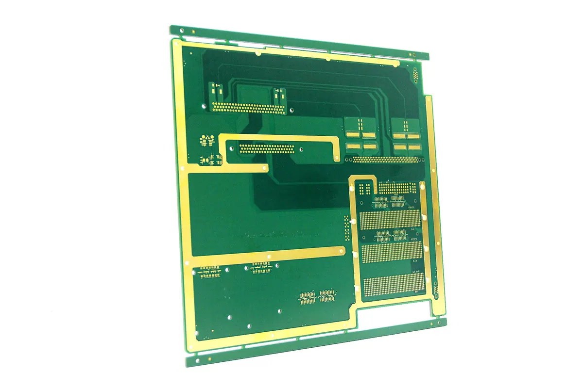
Direct Answer
PCB copper thickness is calculated by converting copper foil weight into linear depth (1 oz/ft² equals ~1.37 mils or 34.8 µm) and adding electrolytic plating thickness for finished outer layers. For standard multi-layer boards, internal signal layers use raw foil weight (typically 0.5 oz or 1 oz), while external layers begin as base foil and gain approximately 0.7 to 1.4 mils of plated copper during through-hole processing.
Determining the correct copper thickness requires balancing thermal current capacity, impedance targets, minimum line/space rules, and mechanical durability. While 1 oz/ft² (35 µm) finished outer copper serves as the default baseline for standard rigid boards, high-current or high-density interconnect designs require explicit mathematical modeling using IPC-2221 thermal charts alongside plating tolerance adjustments.
Nominal vs. Finished Copper Thickness: Base Foil and Plating Buildup
Calculating true PCB copper thickness requires distinguishing between starting base copper foil thickness and final processed thickness after electroplating and surface finishing. Printed circuit boards use standard weight designations derived from the weight of copper spread evenly over one square foot of laminate.
Base copper foil specifications follow strict material standards under IPC-4101. On inner layers, copper thickness remains essentially static after etching because no additional electroplating takes place. On outer layers, pattern plating adds a significant layer of electrolytic copper into plated through-holes (PTH) and onto surface features.
| Standard Designation | Nominal Mass (oz/ft²) | Nominal Thickness (mils) | Nominal Thickness (µm) | Typical Outer Finished Range (µm) |
|---|---|---|---|---|
| 0.33 oz (1/3 oz) | 0.33 | 0.46 | 11.8 | 25 – 35 (after plating) |
| 0.50 oz (1/2 oz) | 0.50 | 0.68 | 17.5 | 35 – 45 (after plating) |
| 1.00 oz (1 oz) | 1.00 | 1.37 | 34.8 | 45 – 55 (after plating) |
| 2.00 oz (2 oz) | 2.00 | 2.74 | 69.6 | 80 – 95 (after plating) |
| 3.00 oz (3 oz) | 3.00 | 4.11 | 104.4 | 115 – 130 (after plating) |
When designing outer layers, assuming a 1 oz base foil yields a 1 oz finished trace is a frequent miscalculation. Subtractive outer-layer processing begins with a thin base foil—typically 0.5 oz (17.5 µm)—and electroplates roughly 20 to 25 µm (0.8 to 1.0 mil) of additional copper onto the trace tops and sidewalls to achieve a nominal 1 oz (35 µm to 45 µm) finished baseline. Fabricators like Omini verify these microsection dimensions during quality testing using IPC-TM-650 test methods to confirm minimum copper plating thickness inside via barrels and across fine traces.
> Manufacturing Rule-of-Thumb: Never specify base copper weight on final assembly drawings without declaring whether the callout represents minimum base foil or total finished copper thickness. Misinterpreting outer-layer plating allowance is a primary cause of impedance drift and tight-pitch bridging.
Calculating Trace Current Capacity with IPC-2221 Formulations
Calculating the required copper cross-sectional area for power traces depends on acceptable temperature rise ($\Delta T$), continuous direct or root-mean-square current ($I$), and thermal dissipation efficiency of the surrounding dielectrics.
The classical design baseline defined in IPC-2221 utilizes an empirical curve-fit formula to calculate cross-sectional area:
$$A = \left( \frac{I}{k \cdot \Delta T^{0.44}} \right)^{\frac{1}{0.725}}$$
Where:
- $A$ is the required trace cross-sectional area in $mil^2$.
- $I$ is the maximum continuous current in Amperes ($A$).
- $\Delta T$ is the allowable temperature rise above ambient in degrees Celsius ($^\circ C$).
- $k$ is a derating constant: $k = 0.048$ for external layers (exposed to ambient air/convection) and $k = 0.024$ for internal layers (encapsulated by FR-4 dielectrics).
Once you calculate cross-sectional area $A$, determine trace width $W$ by dividing $A$ by the effective copper thickness $H$:
$$W = \frac{A}{H \cdot 1.378}$$
Where $W$ is trace width in mils, $A$ is in $mil^2$, and $H$ is total finished copper weight in $oz/ft^2$.
Numerical Example: High-Current Power Rail
Consider an internal power trace designed to carry 5 Amperes with a maximum allowable temperature rise ($\Delta T$) of 10°C:
1. Apply internal layer constant $k = 0.024$. 2. Calculate cross-sectional area: $$A = \left( \frac{5}{0.024 \cdot (10)^{0.44}} \right)^{1.379} \approx \left( \frac{5}{0.0661} \right)^{1.379} \approx (75.64)^{1.379} \approx 382.4 \text{ mil}^2$$ 3. If using standard 1 oz internal copper ($H = 1.37 \text{ mils}$): $$W = \frac{382.4 \text{ mil}^2}{1.37 \text{ mils}} \approx 279 \text{ mils } (7.08 \text{ mm})$$ 4. If upgrading to 2 oz internal copper ($H = 2.74 \text{ mils}$): $$W = \frac{382.4 \text{ mil}^2}{2.74 \text{ mils}} \approx 139.5 \text{ mils } (3.54 \text{ mm})$$
Doubling the copper thickness cuts the required trace width in half, allowing high-power routing through constrained board channels.
High-Frequency and RF Implications: Skin Depth and Impedance Control
In high-speed digital and RF designs, copper thickness directly dictates signal attenuation, conductor losses, and characteristic impedance ($Z_0$). Selecting thicker copper is not always advantageous for high-frequency routing due to skin effect losses and trapezoidal etch profiles.
Alternating current at elevated frequencies flows predominantly along the outer perimeter of a conductor. The effective skin depth ($\delta$) represents the depth at which current density drops to $1/e$ (roughly 37%) of its surface value:
$$\delta = \sqrt{\frac{\rho}{\pi \cdot f \cdot \mu_0 \cdot \mu_r}}$$
Where $\rho$ is copper resistivity ($1.68 \times 10^{-8} \, \Omega\cdot\text{m}$), $f$ is operating frequency, $\mu_0$ is magnetic permeability of free space, and $\mu_r$ is relative permeability ($\approx 1$ for copper).
At 1 GHz, the skin depth of copper is approximately 2.06 µm (0.081 mils). At 10 GHz, skin depth reduces to 0.66 µm. Because high-frequency energy flows almost entirely within the outermost skin of the conductor, increasing total copper thickness beyond $3\delta$ yields no reduction in AC resistance.
Furthermore, line impedance calculations must account for the cross-sectional shape of etched copper lines. Subtractive chemical etching dissolves metal laterally while cutting vertically, converting an ideal rectangular conductor into a trapezoid.
To maintain precise impedance matching on high-frequency signals, designers evaluating dielectric stacks often consult technical resources like How Do I Select RF PCB Materials? to balance laminate dielectric constant ($\varepsilon_r$) against trace thickness constraints. When choosing specialized substrates, engineering guidelines in How Do You Select RF PCB Material and the Most Commonly Used Types? provide deeper material loss tangents and foil profile specifications.
Manufacturing Constraints: Etching Tolerances, Aspect Ratios, and Solder Mask
Chemical etching creates physical boundaries on minimum line width and space ratios based on copper foil weight. Thicker copper foil requires longer exposure to chemical etchants, increasing lateral undercut and necessitating wider isolation gaps.
Fabrication capabilities restrict minimum feature geometries according to baseline copper thickness:
- 0.5 oz (17.5 µm) starting copper: Minimum line/space down to 3.0 / 3.0 mils (75 / 75 µm).
- 1.0 oz (35 µm) starting copper: Minimum line/space down to 4.0 / 4.0 mils (100 / 100 µm).
- 2.0 oz (70 µm) starting copper: Minimum line/space expands to 6.0 / 6.0 mils (150 / 150 µm).
- 3.0 oz (105 µm) heavy copper: Minimum line/space expands to 10.0 / 10.0 mils (250 / 250 µm).
For flexible or rigid-flex circuits, dynamic bend radii further limit acceptable copper weights. The Flex PCB Manufacturing Process: Materials Selection, Etching, & Lamination overview outlines how heavy copper layers induce high mechanical stresses during flexure, frequently causing copper cracking at fold lines.
Solder Mask Registration and Clearance Drops
Heavy copper traces (2 oz and above) create steep vertical wall steps on outer PCB surfaces. Liquid photo-imageable (LPI) solder mask flows across these steps, pooling at trace bases while thinning over sharp upper corners.
To prevent solder mask pooling, voiding, or flaking: 1. Increase minimum solder mask dam clearances around heavy copper features. 2. Require multi-coat solder mask applications for heavy copper layers exceeding 3 oz. 3. Verify fine-pitch component layout compatibility. When routing dense BGAs or fine-pitch QFPs over thick copper, review Common DFM Issues and How to Avoid Them in PCB Design to eliminate mask alignment failures before tooling releases.
Dense surface mount components with fine pitch leads cannot be placed directly over heavy copper planes without risking bridging or tombstoning. Specialized land geometry guidelines detailed in SMD vs NSMD BGA Pad Design for PCB Assembly help clarify how pad definition influences solder mask dam retention on outer layer copper structures.
Common DFM Mistakes in Copper Weight Selection
DFM engineers regularly identify systematic errors during stackup verification and front-end engineering reviews. Avoiding these common mistakes reduces scrap rates and engineering change orders (ECOs):
- Specifying heavy copper on outer layers containing fine-pitch BGAs: Attempting to route 0.4 mm or 0.5 mm pitch BGA packages on 2 oz outer copper leads to DRC violations because minimum line/space rules cannot be maintained between BGA escape vias.
- Ignoring internal layer plating limitations: Assuming inner layers can receive electroplated copper. Inner layers are fabricated using sub-additive or subtractive processing on raw copper foil without electroplating. Inner copper thickness must strictly match standard foil availability.
- Failing to adjust plane clearances for heavy copper: Using standard 8-mil isolation clearances on 3 oz power planes leads to internal shorting or resin starvation during prepreg lamination, as resin cannot fill deep isolation channels without specialized prepreg glass styles.
- Overspecifying copper weight without checking thermal relief pads: Solidly connecting thick copper planes (2 oz+) to surface mount component pads creates massive heat sinks during assembly reflow, causing cold solder joints and insufficient wetting.
Fabrication Review Checklist and Decision Table
Use this practical checklist table during design reviews to match copper thickness selection against mechanical, electrical, and thermal manufacturing constraints.
| Design Parameter | Standard Signal / Mixed | High-Current / Power Supply | High-Speed / Controlled Z | Heavy Copper / Industrial |
|---|---|---|---|---|
| Primary Driver | Routing Density & Cost | Thermal & Current Limits | Skin Effect & Line Width | Continuous Power Density |
| Typical Outer Copper | 1.0 oz (35 µm) finished | 2.0 oz (70 µm) finished | 0.5 oz – 1.0 oz finished | 3.0 oz – 4.0 oz finished |
| Typical Inner Copper | 0.5 oz or 1.0 oz foil | 1.0 oz or 2.0 oz foil | 0.5 oz foil | 2.0 oz or 3.0 oz foil |
| Min Trace / Space | 3.5 / 3.5 mils | 6.0 / 6.0 mils | 3.0 / 3.0 mils | 10.0 / 10.0 mils |
| Min Via Hole Size | 0.20 mm (8 mils) | 0.30 mm (12 mils) | 0.15 mm (6 mils) microvia | 0.40 mm (16 mils) |
| Applicable Standards | IPC-2221 / IPC-6012 | IPC-2221 / IPC-6012 | IPC-2221 / IPC-2141 | IPC-2221 / IPC-6012 |
| DFM Verification Point | Standard etch check | Thermal relief geometry | Trapezoidal etch factor | Lamination resin fill |
When finalizing fabrication specifications, partner early with full-service assembly and manufacturing providers like Omini. Reviewing raw material stackups, plating parameters, and line-width allowances prior to gerber release ensures optimal assembly yield, strict impedance control, and reliable field performance.