
Direct Answer
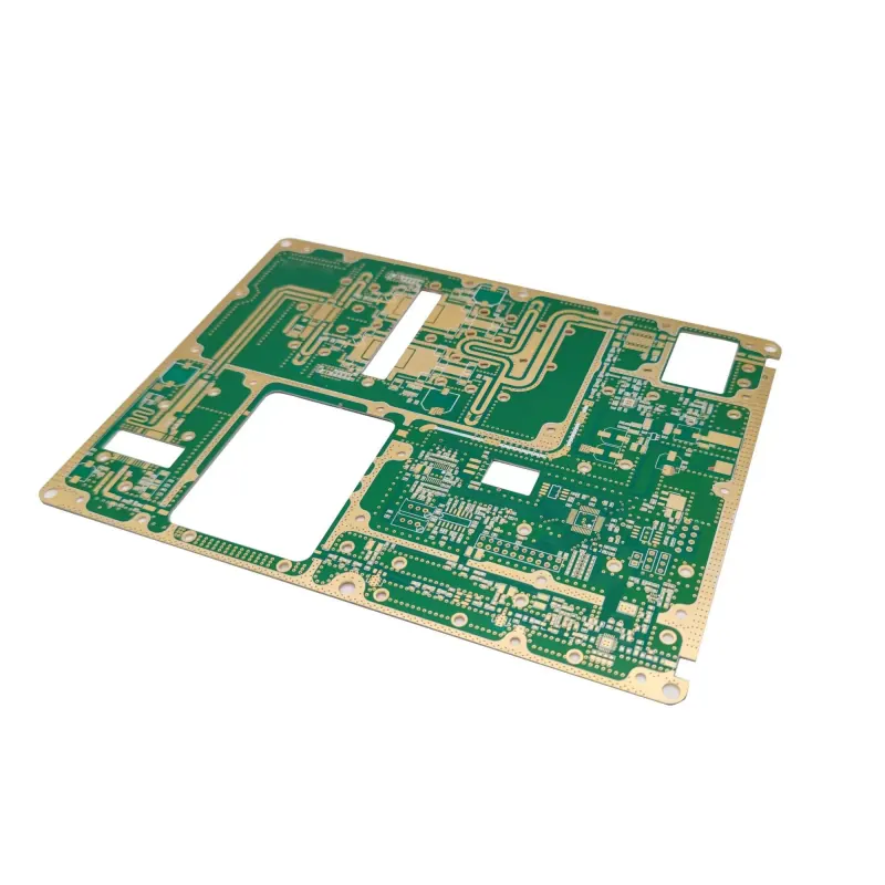
Use Rogers RO4350B when the PCB has RF or microwave paths where FR-4 loss, dielectric tolerance, or thermal expansion would consume too much margin. It is not the cheapest RF material and it is not a generic FR-4 upgrade. Its value comes from a controlled Dk, low Df, and lower Z-axis CTE than many standard glass/epoxy laminates.
Specification Snapshot
| Property | RO4350B value | Engineering note |
|---|---|---|
| Material family | Hydrocarbon ceramic laminate with woven glass | Thermoset RF laminate, not PTFE |
| Process Dk | 3.48 +/- 0.05 at 10 GHz | Use design Dk and final stackup data for impedance |
| Design Dk | 3.66 | Rogers publishes this for circuit design correlation |
| Dissipation factor | 0.0037 at 10 GHz | Lower loss than standard FR-4, higher than RO4003C |
| Thermal conductivity | 0.69 W/m-K | Helps, but copper and via design still dominate heat spreading |
| CTE, X/Y/Z | 10 / 12 / 32 ppm/C | Low Z-axis CTE is useful for plated-through-hole reliability |
| Water absorption | 0.05 percent | Low moisture uptake supports RF stability |
| Flame rating | UL 94 V-0 | One reason to choose it over RO4003C |
Why Engineers Choose RO4350B
The first-order problem is loss and repeatability. FR-4 can work for short RF runs and tolerant wireless modules, but its dielectric constant and loss tangent vary more with resin system, glass weave, frequency, and temperature. At microwave frequencies, that variation changes impedance, phase delay, antenna tuning, filter response, and insertion loss.
RO4350B gives the RF designer a tighter material starting point. That does not remove the need for stackup control. It means the fabricator and designer can converge on a controlled impedance geometry with fewer unknowns than a vague "FR-4 or equivalent" note.
Where RO4350B Fits Best
RO4350B is a strong fit for:
- RF power amplifier boards
- Base-station and telecom RF sections
- Patch antennas, couplers, filters, and matching networks
- Microwave sensor boards
- Hybrid boards with RF layers and standard digital/control sections
It is usually overkill for low-speed control electronics, short 2.4 GHz traces with generous margin, or prototypes where the RF section is not being validated. In those cases, start with the actual electrical requirement before paying for specialty laminate.
Stackup and DFM Notes
Specify RO4350B by exact material name, dielectric thickness, copper foil type, copper weight, and impedance target. Do not write only "Rogers material" or "low-loss laminate." Different RO4000 family materials have different Dk, Df, CTE, flame rating, and availability.
The fabricator should confirm pressed dielectric thickness, copper roughness, etch compensation, drill parameters, and test coupon design before release. RO4350B can process closer to FR-4 than PTFE, but RF performance is still sensitive to small changes in trace width, dielectric thickness, copper treatment, and solder mask coverage.
Hybrid stackups need extra attention. Mixing RO4350B with FR-4 can reduce cost, but the lamination cycle, CTE mismatch, registration, and warpage risk must be checked before material is ordered.
Worked Example
A 4-layer RF module uses a 50 ohm microstrip for a power amplifier output, a compact matching network, and an antenna feed. On standard FR-4, the simulated insertion loss and phase drift leave little margin after enclosure and temperature effects. Moving only the RF dielectric layer to RO4350B gives the design a more stable Dk and lower loss while keeping digital routing and power distribution on lower-cost layers.
The correct manufacturing instruction is not "use Rogers." A better release note is: RO4350B on the RF layer, controlled 50 ohm impedance, fabricator-proposed dielectric thickness for approval, specified copper foil, impedance coupon, and no material substitution without written approval.
Comparison
| Material | Best use | Main tradeoff |
|---|---|---|
| RO4350B | RF boards needing UL 94 V-0, lower Z-axis CTE, and stable Dk | Higher cost than FR-4 and slightly higher loss than RO4003C |
| RO4003C | Cost-sensitive microwave and RF boards where UL 94 V-0 is not required | Not UL 94 V-0 rated |
| FR4 Tg170 | Multilayer industrial boards needing higher thermal robustness than standard FR-4 | Higher loss and looser RF behavior |
| MEGTRON 6 | High-speed digital backplanes and low-loss serial links | Usually selected for digital channel loss, not RF tuning |
Datasheet References
Summary
RO4350B is a practical RF laminate when the design needs better dielectric control than FR-4 and a fabrication path closer to epoxy/glass than PTFE. Choose it because the RF budget requires it, not because "Rogers" sounds premium. The release package should lock the material, thickness, copper, impedance target, and substitution rule before the quote is finalized.