
Direct Answer
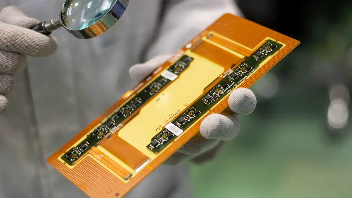
Flex circuit boards, also known as flexible printed circuits or flex PCBs, are electronic interconnections built on thin, flexible dielectric substrates like polyimide or polyester. Unlike rigid PCBs, they can bend, twist, and conform to dynamic or space-constrained environments, making them ideal for applications where movement or compact packaging is required. Their construction typically involves laminated copper traces on a flexible base, often covered with a protective overlay or coverlay.
These boards eliminate the need for bulky connectors and wire harnesses in moving parts, reducing assembly complexity and improving reliability by minimizing interconnect points. Common uses include display connections in laptops, sensor interfaces in medical devices, antenna systems in aerospace, and interconnects in automotive electronics. The flexibility allows for three-dimensional routing that rigid boards cannot achieve.
Material Selection and Construction
The foundation of a reliable flex circuit begins with substrate choice. Polyimide is the most common dielectric due to its excellent thermal stability, chemical resistance, and mechanical durability over repeated flex cycles. Polyester offers a lower-cost alternative for static or low-flex applications but lacks the high-temperature performance needed for soldering or harsh environments.
Copper foil selection is equally important. Rolled annealed (RA) copper provides superior flexibility and fatigue resistance compared to electrodeposited (ED) copper, making it preferred for dynamic flex areas. Adhesiveless laminates, where copper is directly cast onto the polyimide, further enhance flexibility and reduce thickness by eliminating adhesive layers that can crack under stress.
Coverlay or cover coat materials protect the outer copper traces from oxidation, contamination, and mechanical damage. Typically made of polyimide with an adhesive layer, coverlay must be compatible with the substrate and applied without wrinkles or bubbles to prevent delamination. Photoimageable coverlay options allow for finer feature resolution in high-density designs.
Design Considerations for Flexibility and Reliability
Designing flex circuits requires attention to mechanical constraints that do not apply to rigid boards. Bend radius is a critical parameter—it must be large enough to prevent copper trace fatigue or substrate cracking. As a rule of thumb, the minimum bend radius should be at least 10 times the total thickness of the flex stack for dynamic applications, and 5 times for static bends.
Strain relief features, such as teardrop anchors or fillets at trace-to-pad transitions, help distribute mechanical stress and prevent trace lifting. Via placement should avoid high-strain areas; if vias are necessary in bend zones, they require special reinforcement like tenting or via-in-pad designs with plated overlays.
Copper weight also influences flexibility. Thinner copper (e.g., 1/3 oz or 1/2 oz) improves bendability but reduces current-carrying capacity. Designers must balance electrical requirements with mechanical needs, often using thicker copper only in power traces while keeping signal lines thin.
Applications Across Industries
Flex circuits enable innovations where rigid boards fail. In consumer electronics, they connect folding displays in smartphones and tablets, allowing seamless movement without signal degradation. Wearable devices rely on flex circuits to conform to the body’s contours, integrating sensors, batteries, and antennas into lightweight, comfortable form factors.
Medical electronics use flex circuits in implantable devices, endoscopic tools, and wearable monitors, where biocompatibility, sterilization resistance, and dynamic flexing are essential. Aerospace applications include satellite panel interconnects and avionics wiring, where weight savings and vibration resistance are critical. In automotive systems, flex circuits appear in steering wheel controls, sensor arrays, and LED lighting assemblies, enduring thermal cycling and constant vibration.
Industrial equipment benefits from flex circuits in robotic arms, rotating sensors, and movable test fixtures, where repeated motion would quickly fatigue rigid board interconnects. Their ability to eliminate connectors also reduces failure points in high-vibration environments.
Manufacturing Process and Quality Control
Flex circuit fabrication follows many steps similar to rigid PCB production but requires specialized handling. The process starts with substrate preparation, followed by copper lamination, photoresist application, exposure, and development. Etching defines the copper traces, and any plated through-holes or vias are added before coverlay lamination.
Lamination of the coverlay must occur under controlled temperature and pressure to avoid entrapping air or causing adhesive squeeze-out. After lamination, surface finishes like ENIG or immersion tin are applied to exposed pads for solderability. Final steps include cutting or punching the flex to shape, stiffener attachment if needed, and electrical testing.
Quality control begins with material inspection—incoming polyimide and copper rolls are checked for thickness, uniformity, and defects. During production, automated optical inspection (AOI) systems adapted for flex materials detect opens, shorts, and spacing violations. Because flex circuits are often thin and reflective, AOI lighting and algorithms must be tuned to avoid false calls.
X-ray inspection is used to verify internal layer alignment, via integrity, and voids in plated features, especially in multilayer flex or rigid-flex assemblies. For high-reliability applications, cross-sectioning may be performed to assess laminate adhesion and copper thickness.
Electrical testing includes continuity and isolation checks, often performed on a flying probe tester due to the lack of standardized tooling for flex panels. Functional testing may follow final assembly, particularly when flex circuits are integrated into sub-assemblies like connectors or sensor modules.
Testing and Inspection Best Practices
Ensuring flex circuit reliability requires inspection methods that account for their unique failure modes. Standard AOI systems may miss subtle defects like micro-cracks in coverlay or trace lifting under stress. Specialized flex-oriented AOI uses angled lighting and polarization to highlight delamination or adhesion issues.
X-ray inspection excels at detecting internal layer misregistration, voids in plated through-holes, and insufficient adhesive coverage under coverlay. It is non-destructive and ideal for sampling during production or first-article inspection.
For dynamic flex applications, cyclic flex testing simulates real-world bending to validate lifetime performance. Samples are flexed repeatedly to a specified radius while monitoring electrical continuity. This test reveals weaknesses in trace adhesion, copper fatigue, or coverlay brittleness that static inspection might miss.
In-line monitoring during lamination and coverlay application helps prevent process-related defects. Parameters like temperature, pressure, and line speed are tracked to ensure consistent bonding. Post-lamination bake-out cycles can remove moisture and improve adhesion strength.
Reliability Through Process Control and Partnership
Reliability in flex circuit manufacturing is not accidental—it results from disciplined process control, material traceability, and design for manufacturability (DFM) collaboration. Omini works closely with customers during Gerber and BOM review to identify potential flex-specific risks, such as insufficient bend radius, improper strain relief, or incompatible material combinations.
During SMT assembly, flex circuits often require specialized fixtures to prevent movement or deformation during solder paste printing and component placement. Low-tension conveyor systems and vacuum pallets help maintain registration without inducing stress. Reflow profiles must account for the thin substrate’s rapid heat response to avoid thermal damage.
Inspection after assembly includes AOI and X-ray to verify solder joint integrity, component placement, and absence of shorts or opens. Functional testing confirms that the flex circuit performs as expected in its intended mechanical state—whether flat, bent, or flexed.
Traceability is maintained throughout, linking each panel to its material lot, process parameters, and test results. This enables rapid response if a field failure occurs, supporting root cause analysis and corrective action.
For Omini RFQs, flex circuit requirements should connect material selection, bend radius, stiffener placement, inspection scope, and functional test needs before release. That evidence-based handoff is more useful than a generic claim that a flex circuit will survive its final application.
Related Omini Engineering Notes
- Circuit Card Assembly Testing: Tips and Best Practice
- AOI and X-Ray Inspection in PCB Assembly
- Custom PCB Board Manufacturer: How to Ensure Quality and Reliability
- Demystifying Flying Probe PCB Testing: The What, Why, and How
- PCB Stack-Up and Signal Integrity for High-Speed Boards