
Direct Answer
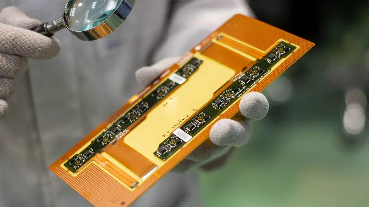
Flexible LED PCBs combine the light-emitting efficiency of LEDs with the mechanical adaptability of flex circuits, enabling lighting solutions that conform to curved, moving, or space-constrained surfaces. Unlike rigid PCBs, they use thin polyimide substrates that bend without cracking, making them ideal for dynamic applications where durability and form factor are critical.
These boards are increasingly used in wearables, automotive lighting, medical devices, and architectural signage. Their ability to integrate LEDs directly onto flexible substrates reduces weight, eliminates connectors, and improves reliability in vibrating environments. However, success depends on proper material selection, layout practices, and manufacturing controls to prevent solder cracks, delamination, or LED misalignment.
Advantages of Flexible LED PCBs
The primary benefit of flexible LED PCBs is their ability to enable three-dimensional lighting layouts that rigid boards cannot achieve. By bending or folding the circuit, designers can follow complex contours in products like curved instrument panels, flexible wearable bands, or foldable displays.
They also reduce system weight and part count. Eliminating wire harnesses or rigid interconnects between LED segments lowers assembly time and potential failure points. In high-vibration environments such as automotive or industrial equipment, the flex circuit’s inherent damping reduces stress on solder joints compared to rigid mounts.
Thermal management is another advantage. Polyimide substrates handle sustained LED operating temperatures well, and thermal vias or copper pours can be designed into the flex layer to spread heat. When paired with aluminum stiffeners or thermal adhesives, flexible LED PCBs can support mid-power LED arrays without overheating.
From a manufacturing standpoint, flexible LED PCBs support panelized production and, in some programs, reel-to-reel processing. The practical RFQ question is which handling method, fixture plan, and inspection scope match the actual LED flex design.
Key Applications in Industry
In automotive design, flexible LED PCBs power interior ambient lighting, door trim illumination, and instrument cluster backlit switches, and seat-edge lighting. Their thin profile allows integration into tight spaces behind panels or under trim pieces where rigidity would prevent installation.
Wearable technology benefits significantly from LED flex circuits. Fitness trackers, medical patches, and smart clothing use them for status indicators, phototherapy, or UV disinfection modules. The ability to wash and bend the circuit without failure is essential here.
Architectural and retail lighting uses flexible LED PCBs in cove lighting, curved signage, and backlit displays. They enable seamless, uniform illumination on non-planar surfaces, reducing shadowing and improving aesthetics.
Medical devices use them in endoscopic tools, flexible sensors, and wearable monitors where biocompatibility and sterilization resistance are required. Proper material selection and encapsulation ensure long-term performance in these environments.
Design Considerations for Manufacturability
Successful flexible LED PCB design starts with material choice. Polyimide is standard for its thermal stability and flex endurance, but adhesive-less versions improve tear resistance and reduce outgassing—important in enclosed or medical applications.
Trace width and spacing must accommodate LED current while maintaining flexibility. Narrow traces increase resistance and heat; too wide reduces bendability. A common approach is to use wider power buses with narrower traces to individual LEDs, balanced for both electrical and mechanical performance.
Component placement is critical. Avoid placing LEDs, resistors, or ICs in areas that will experience repeated bending. Use mechanical simulation or bend testing to identify strain zones. Place components on stiffened sections or neutral bend axes where flex is minimal.
Use teardrop pads and annular ring reinforcement to prevent pad lifting during flexing. Vias should be avoided in bend areas; if necessary, use buried or blind vias in rigidified sections only. Stiffeners (FR4 or polyimide) can be added locally under connectors or components to provide mounting stability without sacrificing overall flexibility.
Solder mask and silkscreen must be flexible-grade to prevent cracking. Consider conformal coating for moisture, dust, or chemical resistance, especially in automotive or outdoor applications.
Manufacturing and Assembly Process
For Omini RFQs, flexible LED PCB review should focus on flex-specific risks: bend radius validation, component placement in low-strain zones, and stiffener alignment. Gerber and BOM files should be checked for completeness before SMT setup.
During assembly, precision solder paste printing is essential due to fine-pitch LED packages and potential substrate movement. Vision systems align the flex panel to ensure consistent registration. Low-residue, no-clean solder paste is preferred to avoid contamination that could affect flexibility or optical properties.
Reflow profiling must account for the thin substrate's rapid heat response. The build plan should define how overheating, underheating, delamination risk, and poor solder wetting will be controlled.
Post-assembly, AOI checks component orientation, solder volume, and polarity, which are critical for LEDs. X-ray inspection may be scoped for hidden solder joints when the package type requires it. These checks should tie directly to traceability and release evidence.
Functional testing can verify LED forward voltage, current draw, and uniformity. For high-reliability applications, thermal cycling and mechanical flex testing should be defined before quote if they are part of customer acceptance.
Quality and Reliability Practices
Reliability in flexible LED PCBs hinges on controlling failure modes: solder cracks, delamination, pad lifting, and LED misalignment. The practical control path is design feedback, process controls, and inspection.
Acceptance should reference the standards and project criteria that apply to the order, including LED-specific defects such as insufficient luminance or color shift when those checks are required. Traceability should be defined from panel lot to final assembly, linking boards to inspection data, process records, and test results as needed.
AOI and X-ray inspection should be scoped by package risk. AOI is useful for visible placement and solder defects; X-ray is useful where hidden joints or package geometry make optical inspection insufficient.
Functional test procedures can include dynamic lighting tests under flexed conditions when the product use case requires that evidence.
Material qualification for polyimide laminates, solder pastes, and encapsulants should be part of the buyer file because those materials directly affect flex life and environmental resistance.
Integration with Broader Manufacturing Capabilities
Flexible LED PCBs often serve as part of a larger system. For example, a double-sided flex circuit might connect to a rigid PCB for power distribution or control logic. Understanding the Double Sided PCB: Advantages, Applications, and Manufacturing Process helps designers optimize hybrid rigid-flex assemblies.
Similarly, insights from Flex Circuit Boards: Introduction and Applications: Introduction and Applications provide foundational knowledge on flex materials, bend testing, and surface finishes that apply directly to LED flex designs.
Treat the flexible LED PCB as a critical subsystem subject to the same DFM, inspection, and traceability planning as any PCBA. That is the evidence path needed before release, whether the final product is a wearable sensor or an automotive lighting module.
Field note: When designing flexible LED PCBs, treat bend radius and component placement as first-order constraints—not afterthoughts. A 10-minute bend test on a prototype can prevent weeks of field failure analysis later.
Related Omini Engineering Notes
- Flex Circuit Boards: Introduction and Applications: Introduction and Applications
- AOI and X-Ray Inspection in PCB Assembly
- Circuit Card Assembly Testing: Tips and Best Practice
- Custom PCB Board Manufacturer: How to Ensure Quality and Reliability
- Double Sided PCB: Advantages, Applications, and Manufacturing Process